• Completely self-contained;
no outside condensing unit
• Closet access panel may
be installed in the front,
left or right side of the unit
• Patented telescoping
plenum (accessory)
easily adapts to more
installations
• Unique free-oating
chassis and fully insulated
cabinets for improved
sound characteristics and
unit performance
• Condensate removal
system uses slinger ring
technology to cool the coil
and increase efciency
• Primary condensate
removal system provided
thru 3/4" pipe ttings for
more placement options
• Secondary overow from
primary drain*
• Unit is wired and charged
at the factory
• Two-speed fan control
from wireless or wired
wall thermostat
• Safety power disconnect
• Weighs as little as 125 lbs.
• 5 YR. limited warranty-
includes labor
* 24000 Btu model uses
secondary gravity-fed drain
VERT-I-PAK_Product_Prole_2014
SINGLE PACKAGE
VERTICAL AIR CONDITIONERS
Product Profile
Features
Protects the outdoor coil against
deterioration and extends the
life of the unit especially in
harsh coastal environments.
2
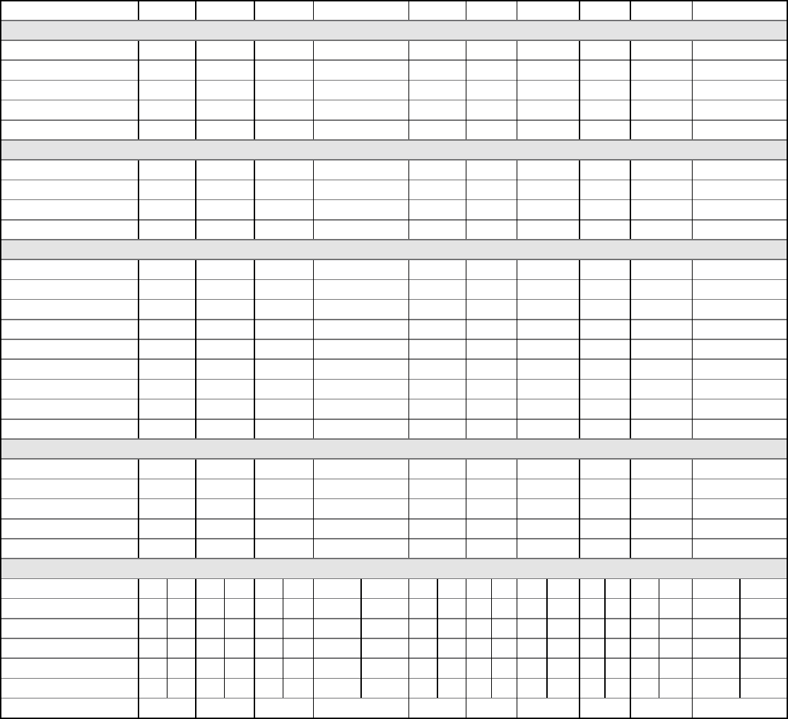
Chassis Specifications
Model VEA09K VEA12K VEA18K VEA24K VHA09K VHA09R VHA12K VHA12R VHA18K VHA24K
COOLING DATA
COOLING Btu 9000/8600 11500/11200 17000/16500 23000/22700 9000/8600 8900 11500/11200 12000 17000/16800 23000/22800
POWER (W) 857/819 1174/1143 1889/1833 2421/2389 857/819 908 1186/1155 1224 1868/1846 2527/2505
EER 10.5/10.5 9.8/9.8 9.0/9.0 9.5/9.5 10.5/10.5 9.8 9.7/9.7 9.8 9.1/9.1 9.1/9.1
SENSIBLE HEAT RATIO 0.74 0.74 0.70 0.70 0.74 0.74 0.74 0.72 0.70 0.70
HEATER SIZE 2.5/3.4/5.0 2.5/3.4/5.0 2.5/3.4/5.0 2.5/3.4/5.0/7.5/10.0 2.5/3.4/5.0 2.5/3.4/5.0 2.5/3.4/5.0 2.5/3.4/5.0 2.5/3.4/5.0 2.5/3.4/5.0/7.5/10.0
HEAT PUMP DATA
HEATING Btu — — — — 8200/8000 8700 10800/10600 11500 16000/15000 20000/20000
COP @ 47F — — — — 3.0/3.0 3.0 3.0/3.0 3.0 3.0/3.0 3.0/3.0
HEATING POWER (W) — — — — 801/782 850 1055/1035 1123 1560/1540 1953/1953
HEATING CURRENT (A) — — — — 3.6/3.9 3.4 4.5/4.7 4.4 7.5/8.2 8.5/9.4
ELECTRICAL DATA
VOLTAGE (1 PHASE, 60 Hz) 230/208 230/208 230/208 230/208 230/208 265 230/208 265 230/208 230/208
VOLT RANGE 253-187 253-187 253-187 253-187 253-187 292-239 253-187 292-239 253-187 253-187
COOLING CURRENT (A) 4.0/4.3 5.2/5.4 8.1/8.6 10.0/10.4 4.0/4.3 3.6 5.3/5.5 5.0 8.2/8.6 10.6/10.9
AMPS L.R 21.0 29.5 42.0 46 21.0 16.5 29.5 23.5 42.0 46.0
AMPS F.L. 3.5 4.5 7.8 9.5 3.5 3.1 5.0 4.3 7.8 9.5
INDOOR MOTOR (HP) 1/4 1/4 1/4 1/4 1/4 1/4 1/4 1/4 1/4 1/4
INDOOR MOTOR (A) 1.2 1.2 1.2 1.94 1.2 1.08 1.2 1.08 1.2 1.94
OUTDOOR MOTOR (HP) — — — 1/4 — — — — — 1/4
OUTDOOR MOTOR (A) — — — 0.85 — — — — — 0.85
PHYSICAL
DIMENSIONS (W x D x H) 23”x23”x32” 23”x23”x32” 23”x23”x32” 23”x23”x47” 23”x23”x32” 23x23x32 23”x23”x32” 23x23x32 23”x23”x32” 23”x23”x47”
NET WEIGHT (LBS) 114 124 144 167 114 114 125 124 144 167
SHIPPING WEIGHT (LBS) 125 135 155 220 125 125 135 135 155 220
TEST SETTING Low Low High Low Low Low Low Low High Low
R410A CHARGE (OZ) 41.5 32 48.1 65 38 39 39 37 48 65
AIRFLOW DATA
INDOOR CFM* Low High Low High Low High Low High Low High Low High Low High Low High Low High Low High
.10” ESP 405 450 420 450 400 480 610 700 420 450 420 450 420 450 420 450 400 480 610 700
.15” ESP 375 420 405 425 375 465 585 670 405 425 405 425 405 425 405 425 375 465 585 670
.20” ESP 345 385 385 400 350 450 560 640 385 400 385 400 385 400 385 400 350 450 560 640
.25” ESP 325 365 355 375 330 390 535 610 355 375 355 375 355 375 355 375 330 390 535 610
.30” ESP 305 340 320 350 310 330 510 580 320 350 320 350 320 350 320 350 310 330 510 580
VENT CFM 60 60 60 60
60 60 60 60 60 60
3
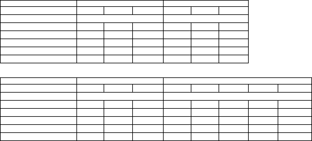
Electric Heat Data
Electric Heat Data
VE/VHA09 VE/VHA12
HEATER WATTS 2500/2050 3400/2780 5000/4090 2500/2050 3400/2780 5000/4090
VOLTAGE 230/208 230/208
HEATING Btu 8500/7000 11600/9500 17000/13900 8500/7000 11600/9500 17000/13900
HEATING CURRENT (AMPS) 10.9/9.9 14.8/13.4 21.7/19.7 10.9/9.9 14.8/13.4 21.7/19.7
MINIMUM CIRCUIT AMPACITY 15 19.9 28.6 15 19.9 28.6
BRANCH CIRCUIT FUSE (AMPS) 15 20 30 15 20 30
BASIC HEATER SIZE 2.5 Kw 3.4 Kw 5.0 Kw 2.5 Kw 3.4 Kw 5.0 Kw
Electric Heat Data
VE/VHA18 VE/VHA24
HEATER WATTS 2500/2050 3400/2780 5000/4090 2500/2050 3400/2780 5000/4090 7500/6135 10000/8180
VOLTAGE 230/208 230/208
HEATING Btu 8500/7000 11600/9500 17000/13900 8500/7000 11600/9500 17000/13900 25598/20939 34130/27918
HEATING CURRENT (AMPS) 10.9/9.9 14.8/13.4 21.7/19.7 10.9/9.9 14.8/13.4 21.7/19.7 32.6/29.5 43.5/39.3
MINIMUM CIRCUIT AMPACITY 15 19.9 28.6 17.2/15.9 22.1/20.3 30.7/28.1 44.3/40.3 57.9/52.7
BRANCH CIRCUIT FUSE (AMPS) 15 20 30 25 25 30 45 60
BASIC HEATER SIZE 2.5 Kw 3.4 Kw 5.0 Kw 2.5 Kw 3.4 Kw 5.0 Kw 7.5 Kw 10.0 Kw
4
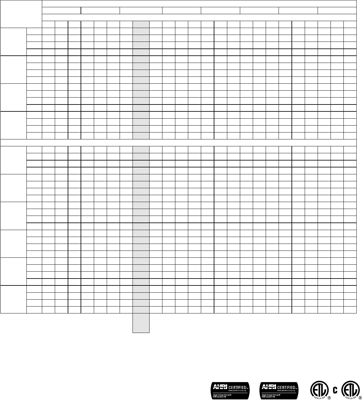
Extended Cooling Performance
OUTDOOR DRY BULB TEMP. (DEGREES F AT 40% R.H.)
75 85 95 105 110 115 120 130
INDOOR WET BULB TEMP. (DEGREES F AT 80 F D.B.)
72 67 62 72 67 62 72 67 62 72 67 62 72 67 62 72 67 62 72 67 62 72 67 62
VEA09KRTM
BTUh 10584 10179 9423 10080 9504 8766 9684 9000 7965 9072 8055 7101 8573 7502 6620 8073 7446 6138 7574 6892 5657 7034 6262 5117
WATTS 699 710 718 762 770 779 857 857 857 926 926 928 968 968 971 1011 1011 1016 1054 1053 1058 1088 1096 1097
AMPS 3.3 3.3 3.4 3.6 3.6 3.6 4 4.00 4.0 4.3 4.3 4.3 4.5 4.5 4.5 4.7 4.7 4.7 4.9 4.9 4.9 5.0 5.1 5.1
SHR 0.51 0.69 0.93 0.52 0.71 0.95 0.52 0.74 0.95 0.53 0.78 0.96 0.55 0.81 0.95 0.56 0.83 0.95 0.57 0.86 0.94 0.58 0.89 0.93
VEA12KRTL
BTUh 13524 13007 12041 12880 12144 11201 12374 11500 10178 11592 10293 9074 10954 9585 8458 10316 9514 7843 9677 8807 7228 8987 8002 6538
WATTS 958 973 984 1044 1054 1067 1174 1174 1174 1269 1268 1271 1327 1326 1331 1385 1385 1391 1444 1443 1450 1491 1502 1503
AMPS 4.1 4.2 4.2 4.5 4.5 4.5 5 5.00 5 5.4 5.4 5.4 6.0 6.0 6.0 6.0 6.0 6.0 6.0 6.0 6.0 6.0 6.0 6.0
SHR 0.49 0.67 0.9 0.5 0.7 0.92 0.51 0.72 0.92 0.52 0.76 0.93 1.00 1.00 1.00 1.00 1.00 1.00 1.00 1.00 1.00 1.00 1.00 1.00
VEA18KRTL
BTUh 19992 19227 17799 19040 17952 16558 18292 17000 15045 17136 15215 13413 16193 14170 12504 15249 14064 11594 14306 13019 10685 13286 11829 9665
WATTS 1541 1566 1583 1679 1696 1717 1889 1889 1889 2042 2040 2046 2135 2134 2141 2229 2228 2238 2323 2322 2333 2399 2416 2418
AMPS 6.7 6.7 6.8 7.2 7.2 7.3 8.1 8.10 8.1 8.7 8.7 8.7 9.0 9.0 9.0 9.0 10.0 10.0 10.0 10.0 10.0 10.0 10.0 10.0
SHR 0.48 0.65 0.88 0.49 0.68 0.89 0.49 0.70 0.9 0.5 0.74 0.9 1.00 1.00 1.00 1.00 1.00 1.00 1.00 1.00 1.00 1.00 1.00 1.00
VEA24KRTL
BTUh 27048 26013 24081 25760 24288 22402 24748 23000 20355 23184 20585 18147 21908 19171 16917 20631 19028 15686 19355 17613 14456 17975 16003 13076
WATTS 1976 2007 2029 2152 2174 2201 2421 2421 2421 2617 2615 2622 2736 2735 2744 2857 2856 2869 2978 2975 2990 3075 3096 3099
AMPS 8.3 8.3 8.4 8.9 9 9 10 10.00 10.1 10.8 10.8
10.8 11.0 11.0 11.0 12.00 12.00 12.00 12.00 12.00 12.00 13.00 13.00 13.00
SHR 0.48 0.65 0.88 0.49 0.68 0.89 0.49 0.70 0.9 0.5 0.74 0.9 0.52 0.76 0.9 0.53 0.79 0.9 0.54 0.81 0.89 0.55 0.84 0.88
VHA09KRTM
BTUh 10584 10179 9423 10080 9504 8766 9684 9000 7965 9072 8055 7101 8573 7502 6620 8073 7446 6138 7574 6892 5657 7034 6262 5117
WATTS 699 710 718 762 770 779 857 857 857 926 926 928 968 968 971 1011 1011 1016 1054 1053 1058 1088 1096 1097
AMPS 3.3 3.3 3.4 3.6 3.6 3.6 4 4.00 4.0 4.3 4.3 4.3 4.5 4.5 4.5 4.7 4.7 4.7 4.9 4.9 4.9 5.0 5.1 5.1
SHR 0.51 0.69 0.93 0.52 0.71 0.95 0.52 0.74 0.95 0.53 0.78 0.96 0.55 0.81 0.95 0.56 0.83 0.95 0.57 0.86 0.94 0.58 0.89 0.93
VHA12KRTL
BTUh 13524 13007 12041 12880 12144 11201 12374 11500 10178 11592 10293 9074 10954 9585 8458 10316 9514 7843 9677 8807 7228 8987 8002 6538
WATTS 968 983 994 1054 1065 1078 1186 1186 1186 1282 1281 1284 1340 1340 1344 1399 1399 1405 1459 1458 1465 1506 1517 1518
AMPS 4.1 4.2 4.2 4.5 4.5 4.5 5.0 5.0 5.0 5.4 5.4 5.4 5.6 5.6 5.6 5.9 5.9 5.9 6.1 6.1 6.2 6.3 6.4 6.4
SHR 0.51 0.69 0.93 0.52 0.71 0.95 0.52 0.74 0.95 0.53 0.78 0.96 0.55 0.81 0.95 0.56 0.83 0.95 0.57 0.86 0.94 0.58 0.89 0.93
VHA18KRTL
BTUh 19992 19227 17799 19040 17952 16558 18292 17000 15045 17136 15215 13413 16193 14170 12504 15249 14064 11594 14306 13019 10685 13286 11829 9665
WATTS 1541 1566 1583 1679 1696 1717 1889 1889 1889 2042 2040 2046 2135 2134 2141 2229 2228 2238 2323 2322 2333 2399 2416 2418
AMPS 6.7 6.7 6.8 7.2 7.2 7.3 8.1 8.10 8.1 8.7 8.7 8.7 9.1 9.1 9.1 9.5 9.5 9.6 9.9 9.9 10.0 10.2 10.3 10.3
SHR 0.48 0.65 0.88 0.49 0.68 0.89 0.49 0.70 0.9 0.5 0.74 0.9 0.52 0.76 0.9 0.53 0.79 0.9 0.54 0.81 0.89 0.55 0.84 0.88
VHA24KRTL
BTUh 2705 2601 2408 2576 2429 2240 2475 2300 2036 2318 2059 1815 2191 1917 1692 2063 1903 1569 1935 1761 1446 1797 1600 1308
WATTS 2062 2095 2118 2247 2269 2297 2527 2527 2527 2732 2729 2737 2856 2854 2864 2982 2981 2994 3108 3106 3121 3209 3232 3235
AMPS 9 9.1 9.2 9.7 9.8 9.8 10.8
10.9 11.0 11.7 11.7 11.8 12.3 12.3 12.3 12.8 12.8 12.9 13.3 13.4 13.4 13.7 13.8 13.9
SHR 0.48 0.65 0.88 0.49 0.68 0.89 0.49 0.7 0.9 0.5 0.74 0.9 0.52 0.76 0.9 0.53 0.79 0.9 0.54 0.81 0.89 0.55 0.84 0.88
VHA09RRTM
BTUh 10466 10066 9318 9968 9398 8669 9576 8900 7877 8971 7966 7022 8477 7418 6546 7983 7363 6070 7489 6816 5594 6955 6193 5060
WATTS 741 753 761 807 815 825 908 908 908 982 981 983 1026 1026 1029 1071 1071 1076 1117 1116 1121 1153 1161 1162
AMPS 3 3 3 3.2 3.2 3.2 3.6 3.6 3.6 3.9 3.9 3.9 4.1 4.1 4.1 4.2 4.2 4.2 4.4 4.4 4.4 4.5 4.6 4.6
SHR 0.51 0.69 0.93 0.52 0.71 0.95 0.52 0.74 0.95 0.53 0.78 0.96 0.55 0.81 0.95 0.56 0.83 0.95 0.57 0.86 0.94 0.58 0.89 0.93
VHA12RRTM
BTUh 14112 13572 12564 13440 12672 11688 12912 12000 10620 12096 10740 9468 11430 10002 8826 10764 9928 8184 10098 9190 7542 9378 8350 6822
WATTS 999 1015 1026 1088 1099 1113 1224 1224 1224 1323 1322 1326 1383 1383 1387 1444 1444 1450 1506 1504 1512 1554 1565 1567
AMPS 4.1 4.2 4.2 4.5 4.5 4.5 5 5 5.0 5.4 5.4 5.4 5.6 5.6 5.6 5.9 5.9 5.9 6.1 6.1 6.2 6.3 6.4 6.4
SHR 0.49 0.67 0.9 0.5 0.7 0.92 0.51 0.72 0.92 0.52 0.76 0.93 0.53 0.79 0.93 0.54 0.81 0.92 0.55 0.84 0.92 0.57 0.86 0.91
RATING
POINT
ARI
310/380
Due to continuing research in new energy-saving technology, specications are subject to change without notice.
5
Vert-I-Pak
®
Single Package Air Conditioners
Model Identication Guide
Electric Heater Size
A Series
25 = 2.5 KW
34 = 3.4 KW
50 = 5.0 KW
75 = 7.5 KW*
10 = 10 KW*
MODEL NUMBER V E A 09 K 34 RT L
Engineering Code
Options
RT = Standard Remote Operation
* 24000 Btu only.
Voltage
K = 208/230V-1Ph-60Hz
Nominal Capacity
A Series (Btu)
09 = 9,000
12 = 12,000
Design Series
A = 32"/47" Cabinet
Series
V=Vertical Series
18 = 18,000
24 = 24,000
E =Cooling with electric heat
H =Heat Pump
Refer to electrical data chart for heater/unit compatibility.
PURCHASER P.O. # DATE
PROJECT LOCATION
ENGINEER ARCHITECT
SUBMITTED BY FOR APPROVAL FOR REFERENCE
ITEM PLAN DESIGNATION QUANTITY COOLING Btu VOLTAGE FRIEDRICH MODEL
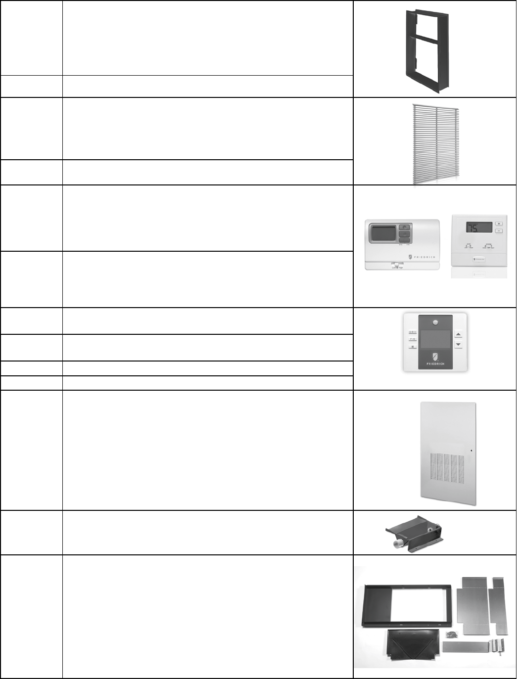
A-Series Accessories (Wall Plenum and Outdoor Louver are required)
VPAWP1-8 Adjustable Wall Plenum (5 ½"- 8") Qty
VPAWP1-14 Adjustable Wall Plenum (8"-14") Qty
VPAL2 Architectural Louver Qty
VPSC2 Architectural Louver (color matched) Qty
VPASA1 Sleeve adapter for
exact t in exist-
ing First Company SPXR-series
Qty
VPRG4 Return Air Grille/Access Panel Qty
VPDP1 Drain Pan for all A Series 24,000 Btu Qty
RT6 Wired Digital Wall Thermostat Qty
WRT1 Wireless Digital Wall Thermostat Qty
EMRT1 Wired Thermostat with Occupancy Sensor Qty
EMWRT1 Wireless Thermostat with Occupancy
Sensor
Qty
EMOCT Online Connection Kit Qty
EMRAF Remote Access Fee Qty
VERT-I-PAK
®
_SUBMITTAL_14
6
Application and Accessories (All models)
• The use of a Friedrich wall plenum is required for installation.
Plenum opening is
3
/
4
" above the oor for 9, 12 and 18k mod-
els, and 1
1
/
2
" for 24k Btu models. (VPAWP1-8 / VPAWP1-14).
• Return air is accommodated with a return air lter attached
to the unit or through the use of a return air lter grille.
(VPRG4).
• Exterior louvers are available in anodized aluminum (VPAL2)
or in custom painted colors (VPSC2).
• Unit is controlled by a remote wall-mounted thermostat.
Friedrich model WRT1 wireless digital thermostat or RT6
wired digital thermostat are recommended.
• Central desk control ready
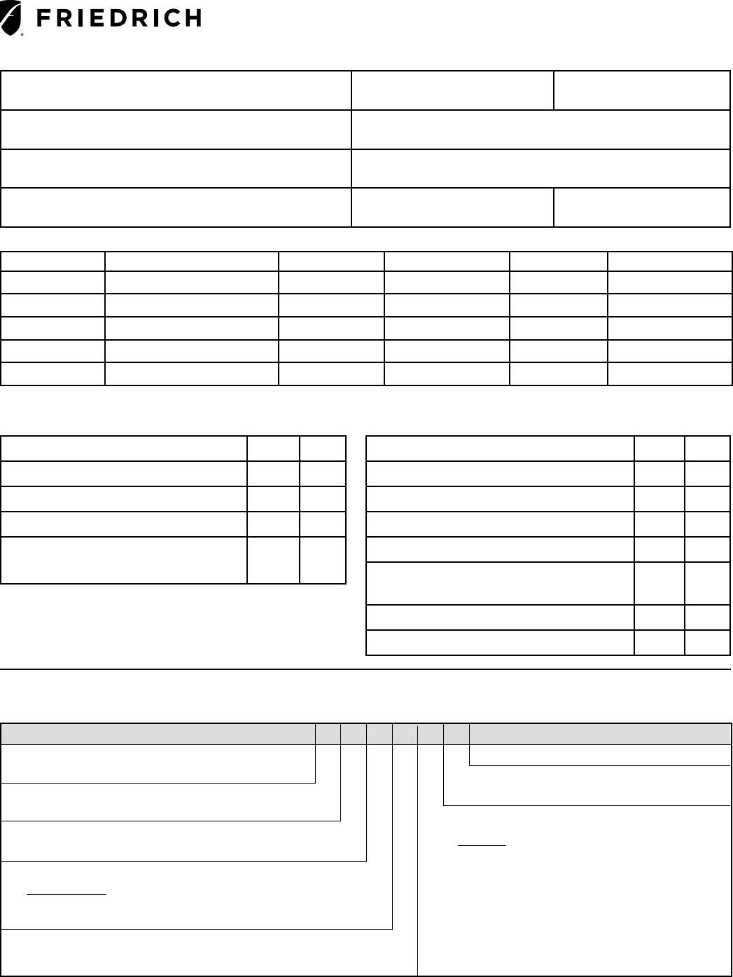
Typical Closet Arrangement
Cutaway of a typical closet shown with Vert-I-Pak
®
chassis
installed in the wall sleeve. The unit has the thermostat, eld
wiring, internal drain and ex duct attached. VPRG4 return air
lter holder and access panel are shown to the right.
The closet access panel may be installed in the front (as
shown below) or to the left or right side of the unit. All three
installation options will allow access to the unit for removal
and replacement.
Application and Installation
Installation Guidelines
• Chassis is to be installed against an exterior wall. Wall
cutout dimensions will be 24 5/8" w x 30 7/8" h.
• Closet should allow for a minimum of three inches on three
sides of the unit for return air, drain connections and change
outs.
• Minimum recommended access door rough-in measure-
ments 27" wide by 55
3
/
4
" high (for VPRG4).
• Friedrich recommends the use of a platform between 24"
and 36" above the oor, for ease of installation and ser vice-
ability.
• Duct outlet designed for external static pressures up to .3"
on 9,000 – 18000 Btu models, and .4" on 24000 Btu models.
• Wall plenum allows chassis to be inserted 2
3
/
8
" into plenum,
thereby minimizing closet dimensions.
• Quick connect drain coupling ships standard to make instal-
lation and removal easier
Application and Accessories (Two-ton Models only)
• New design utilizes drain pan (VPDP1) that can be installed
prior to chassis for simplied installation and removal.
• Utilizes same wall plenum as other units to give consistent
exterior appearance. VEA/VHA24 plenum must be installed
1
1
/
2
" off of chassis platform.
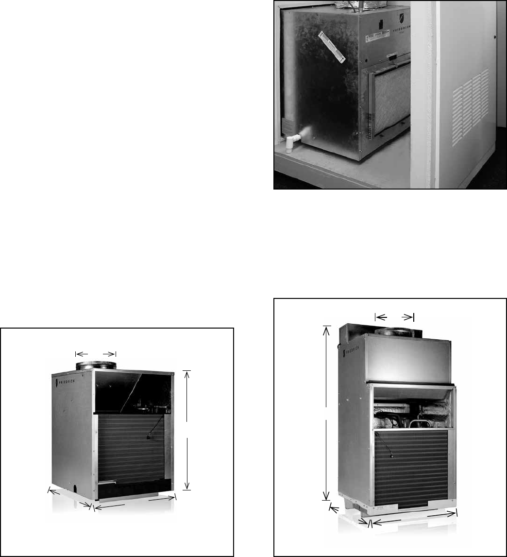
9000 - 18000 Btu
10"
23
1
/
8
"
23
1
/
8
"
32
1
/
4
"
24000 Btu (Two-ton models)
10"
47
1
/
4
"
23
1
/
8
"
23
1
/
8
"
7
VPAWP-1-8
WALL PLENUM Two-part sleeve that telescopes in and out from
5
1
/
2
" to 8" in depth. The wall plenum sits inside the exterior wall
penetration.
DIMENSIONS: 30
3
/
8
" high x 24
1
/
8
" wide.
CUTOUT DIMENSIONS: 30
7
/
8
" high x 24
5
/
8
" wide.
VPAWP1-14 Same as VPAWP1-8, but telescopes 8" to 14" as required.
VPAL2 VPAL2
ARCHITECTURAL LOUVER Extruded aluminum louver that attaches
to the outdoor section of the wall plenum.
DIMENSIONS: 31
1
/
16
" high x 25
9
/
16
" wide.
VPSC2
Same as VPAL2 but can be ordered in custom colors to match the
exterior wall.
RT6 RT6
DIGITAL THERMOSTAT Single stage cool, single stage heat for
VEA and VHA models. Thermostat features high/low fan speed
switch. Thermostat is hard wired and can be battery powered
or unit powered. Features backlight display and multiple
conguration modes.
WRT1 WIRELESS DIGITAL THERMOSTAT
Single stage cool, single stage
heat for VEA and VHA models. Thermostat features high/low fan
speed switch. Thermostat is wireless and is battery powered.
Features backlight display and multiple conguration modes.
RT6 WRT1
EMRT1 Wired thermostat with occupancy sensor
EMWRT1 Wireless thermostat with occupancy sensor
EMOCT Online connection kit
EMRAF Remote access fee EMRT1, EMWRT1
VPRG4 ACCESS PANEL / RETURN AIR GRILLE – Serves as an access panel
to chassis and interior return air grille. A eld-supplied (25" x 20")
lter is mounted inside the hinged access door. Panel can be mounted
with return air openings high or low on the door for optimum sound
attenuation.
DIMENSIONS: 58" high x 29" wide.
CUTOUT DIMENSIONS: 55
3
/
4
" high x 27" wide.
VPDP1 DRAIN PAN for VEA/VHA24 models. Drain pan may be installed prior
to chassis for easy installation/removal.
VPASA1
SLEEVE ADAPTER - Single piece, welded adapter allows retrot into
existing First Company SPXR-series single package vertical unit wall
sleeve and louver. Easy connection to Friedrich chassis.
Accessories
8
All units shall be factory assembled, piped, wired and fully
charged with R-410A. All units shall be certied in accordance
with ARI Standard 390 for Single Packaged Vertical Air Condi-
tioners and Heat Pumps. Units shall be ETL listed and carry a
ETL label. All units shall be factory run-tested to check opera-
tion and be manufactured by Friedrich or equivalent.
The basic unit shall not exceed 23
1
/
8
" wide x 23
1
/
8
" deep. Overall
height of the unit from the bottom of the isolators to the top of the
duct collar shall not exceed 32 ¼" for models up to 18,000 Btu and
47 ¼" for models up to 24,000 Btu. The unit shall be designed so
that the unit will insert into a factory supplied wall plenum 2
3
/
8
"
to minimize room intrusion. Factor y supplied wall plenums shall
allow for installation through walls from 4 ½" – 14" in thickness.
Wall plenums will be adjustable to minimize installation clear-
ances. Unit shall draw in ambient air through upper portion of
an outside architectural louver measuring 25
9
/
16
" wide x 31
1
/
16
"
high and shall exhaust heated air out through the lower portion
of the louver. The unit shall be secured to the architectural lou-
ver by means of a two part, weather-resistant wall plenum. The
unit shall be capable of left, right or straight-in installations into
mechanical closet without eld modications.
REFRIGERATION SYSTEM – The refrigeration system shall be her-
metically sealed and consist of a rotary compressor that is exter-
nally mounted on vibration isolators no smaller than 1 ¾" dia. x 1 ½"
high; condenser and evaporator coils constructed of copper tubes
and aluminum plate ns; and capillaries as expansion devices. Unit
shall have a fan slinger ring to increase efciency and condensate
disposal. A primary condensate removal system consisting of ¾"
FTP ttings on multiple locations shall exist. A secondar y over ow
from the primary drain pan shall expel water to the outside of the
building through the wall plenum and louver in the event that the
primary drain line clogs.
AIR HANDLING SECTION – The condenser fan shall be driven by
a single, totally enclosed, ball bearing, permanently lubricated
split capacitor fan motor for models up to 18,000 Btu. 24,000
Btu models shall utilize a separate motor for both the indoor
and outdoor air sections. Air ow shall be directed vertically up
through a standard 10" ex duct starter collar and into exible
or rigid ducts to be distributed into the conditioned area. Starter
collar shall have both crimped edge to ease ex duct installation
and a waistline to prevent duct from loosening.
The chassis shall have a built-in damper capable of providing
at least 60 CFM of fresh air into the conditioned area. A ne
mesh screen shall lter the incoming fresh air. The damper
can be controlled by a slide lever located on the front of the unit.
CONTROLS – The unit shall be factory equipped with terminal
strip for connection to a standard 24-volt single-stage heat/
cool thermostat. A 24-volt transformer shall be included and
factory wired. Low voltage inputs will include: C (common), R
(24V power), Y (cooling), G (fan), W (heat) and B (reversing valve
on VHA heat pumps only).The unit shall be hard-wired and have
a quick-disconnect to disable power for control box service.
An emergency heat override switch must be available to allow
operation of the resistance heater in the event of a compressor
failure on heat pump models.
GENERAL CONSTRUCTION – The unit shall be constructed of
18-gauge galvanized zinc-coated steel. The unit shall feature
½" foil backed insulation for sound and thermal efciency.
The wall plenum (required factory accessory) shall be shipped
separately and constructed of 20-gauge galvanized zinc-coated
steel; pretreated with zinc-phosphate and sealed with a chro-
mate rinse, then powder-coated for maximum coverage and
protection. The plenum shall be black in color for minimal
visibility of unit from exterior of building. The plenum shall be
shipped with a protective weatherboard for use prior to nal
installation of the louver and chassis.
The architectural louver (required factory accessory) shall
be shipped separately and fabricated from extruded anodized
aluminum with louvers in the horizontal plane.
The unit shall include vibration isolators mounted under the
chassis and a nonrigid plenum-to-chassis connection to isolate
vibrations to the building.
The unit shall have a plastic fan, fan shroud and drain pan and
aluminum outdoor coil endplates for corrosion protection and to
help prevent rust on the side of the building below the outdoor
louver.
The unit shall be shipped with return air lter brackets and a 14"
x 20" lter afxed directly on to the unit chassis. Optional return
air grilles and access panels shall be available as factory acces-
sories for installation in the wall or door of the mechanical closet.
CORROSION PROTECTION - The unit shall feature corrosion
-resistant materials and nish to help prevent deterioration.
The outdoor coil shall have Diamonblue advanced corrosion pro-
tection consisting of hydrophilic-coated ns to prolong the life of
the coil in all applications including seacoast protection.
ACCESSORY ACCESS PANEL - An optional factory-supplied access
panel shall be available to provide access to the unit and adequate
return air. The panel shall feature a lter holder to accept a eld
supplied 25” x 20” x 1” lter. Kit shall contain a hinge bracket for
mounting the door with the return air openings high or low on the
door for optimal sound attenuation. For 9,000 / 12,000 / 18,000
Btu models it is recommended to install the door with the hinge
on the right side and the return air openings high on the door. For
24,000 Btu models it is recommended to install the hinge on the
left with the openings low on the door.
WARRANTY – The warranty is one year on all parts and labor
and 5 years on the sealed system, parts and labor, including
compressor, indoor and outdoor coils and refrigerant tubing.
HVAC Engineering Specifications
A-Series Vertical Packaged Air Conditioners & Heat Pumps
Cooling: 9000 – 23000 Btu
Heating: 8500 – 20000 Btu (Reverse Cycle)
8500 – 34130 Btu (Electric Heat)
Friedrich VEA – Cooling with electric heat
Models: VHA – Heat Pump with electric heat

VERT-I-PAK_Product_ Prole_2014
Friedrich Air Conditioning Company
10001 Reunion Place, Suite 500
San Antonio, TX 78216
800.541.6645
www.friedrich.com
VERT-I-PAK
®
A SERIES
SINGLE PACKAGE VERTICAL AIR CONDITIONERS
LIMITED WARRANTY
SAVE THIS CERTIFICATE. It gives you specific rights. You may also have other rights which may vary from state to state and province to
province.
In the event that your unit needs servicing, contact your nearest authorized service center. If you do not know the nearest service center,
ask the company that installed your unit or contact us - see address and telephone number above. To obtain service and/or warranty parts
replacement, you must notify an authorized FRIEDRICH Air Conditioning Co. service center, distributor, dealer, or contractor of any defect
within the applicable warranty period.
When requesting service: please have the model and serial number from your unit readily available.
Unless specified otherwise herein, the following applies:
FRIEDRICH VERT-I-PAK A SERIES VERTICAL AIR CONDITIONERS AND HEAT PUMPS
LIMITED WARRANTY - FIRST YEAR (Twelve (12) months from the date of installation). Any part found to be defective in the material
or workmanship will be repaired or replaced free of charge by our authorized service center during the normal working hours; and
LIMITED WARRANTY - SECOND THROUGH FIFTH YEAR (Sixty (60) months from the date of installation). ON THE SEALED
REFRIGERATION SYSTEM. Any part of the sealed refrigeration system that is defective in material or workmanship will be repaired or
replaced free of charge (excluding freight charges) by our authorized service center during normal working hours. The sealed refrigeration
system consists of the compressor, metering device, evaporator, condenser, reversing valve, check valve, and the interconnecting tubing.
These warranties apply only while the unit remains at the original site and only to units installed inside the continental United
States, Alaska, Hawaii, Puerto Rico, Mexico and Canada. The warranty applies only if the unit is installed and operated in
accordance with the printed instructions and in compliance with applicable local installation and building codes and good trade
practices. For international warranty information, contact the Friedrich Air Conditioning Company - International Division.
Any defective part to be replaced must be made available to FRIEDRICH in exchange for the replacement part. Reasonable proof must be
presented to establish the date of install, otherwise the beginning date of this certificate will be considered to be our shipment date plus sixty
days. Replacement parts can be new or remanufactured. Replacement parts and labor are only warranted for any unused portion of the
unit’s warranty.
We will not be responsible for and the user will pay for:
1. Service calls to:
A) Instruct on unit operation. B) Replace house fuses or correct house wiring. C) Clean or replace air filters. D) Remove the unit
from its installed location when not accessible for service required. E) Correct improper installations.
2. Parts or labor provided by anyone other than an authorized service center.
3. Damage caused by:
A) Accident, abuse, negligence, misuse, riot, fire, flood, or acts of God. B) Operating the unit where there is a corrosive atmosphere
containing chlorine, fluorine, or any damaging chemicals (other than in a normal residential environment). C) Unauthorized
alteration or repair of the unit, which in turn affects its stability or performance. D) Failing to provide proper maintenance and
service. E) Using an incorrect power source. F) Faulty installation or application of the unit.
We shall not be liable for any incidental, consequential, or special damages or expenses in connection with any use or failure of
this unit. We have not made and do not make any representation or warranty of fitness for a particular use or purpose and there
is no implied condition of fitness for a particular use or purpose. We make no expressed warranties except as stated in this
certificate. No one is authorized to change this certificate or to create for us any other obligation or liability in connection with
this unit. Any implied warranties shall last for one year after the original purchase date. Some states and provinces do not allow
limitations on how long an implied warranty or condition lasts, so the above limitations or exclusions may not apply to you. The provisions of
this warranty are in addition to and not a modification of or subtraction from the statutory warranties and other rights and remedies provided
by law.
Performance of Friedrich’s Warranty obligation is limited to one of the following methods:
1. Repair of the unit
2. A refund to the customer for the prorated value of the unit based upon the remaining warranty period of the unit.
3. Providing a replacement unit of equal value
The method of fulfillment of the warranty obligation is at the sole discretion of Friedrich Air Conditioning.
In case of any questions regarding the provisions of this warranty, the English version will govern.
(11-10)
THIS PAGE INTENTIONALLY LEFT BLANK.
THIS PAGE INTENTIONALLY LEFT BLANK.

VERT-I-PAK_Product_Prole_2014 (06-14)_2
Friedrich Air Conditioning Co. l 10001 Reunion Place, Suite 500 l San Antonio, TX 78216 l 877.599.5665
www.friedrich.com
