VPAK PP FEB-2023 95214200_13
Single Package Vertical Heat Pumps
18000 & 24000 BTU models use secondary gravity-fed
drain (VPDP2).
VERT-I-PAK
®
PRODUCT PROFILE
THE EXPERTS IN ROOM AIR CONDITIONING
PRODUCT PROFILE

2
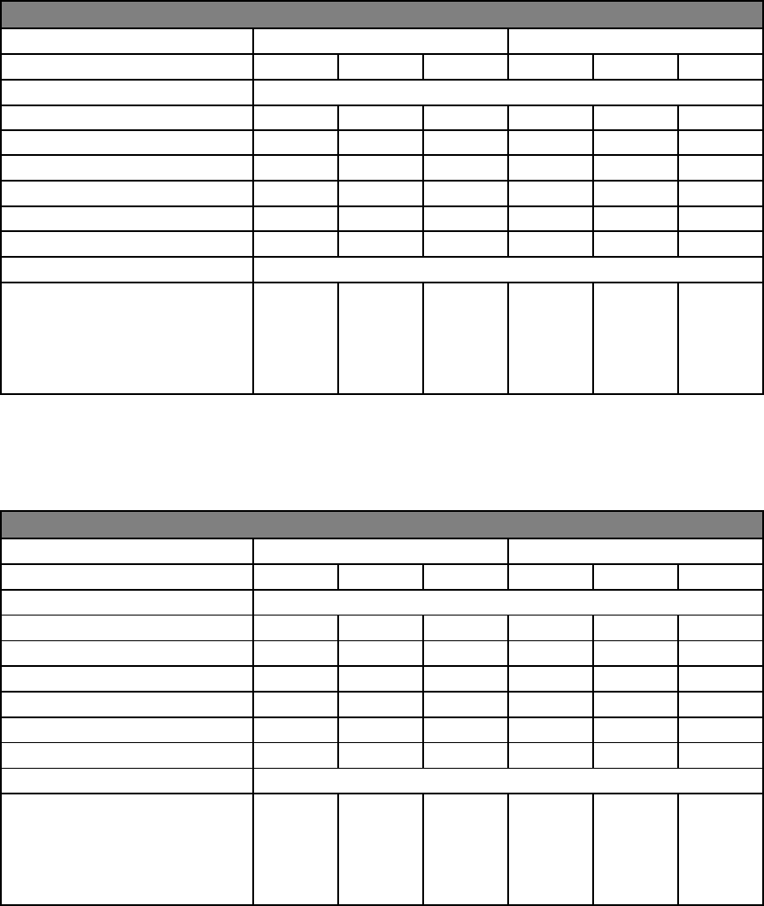
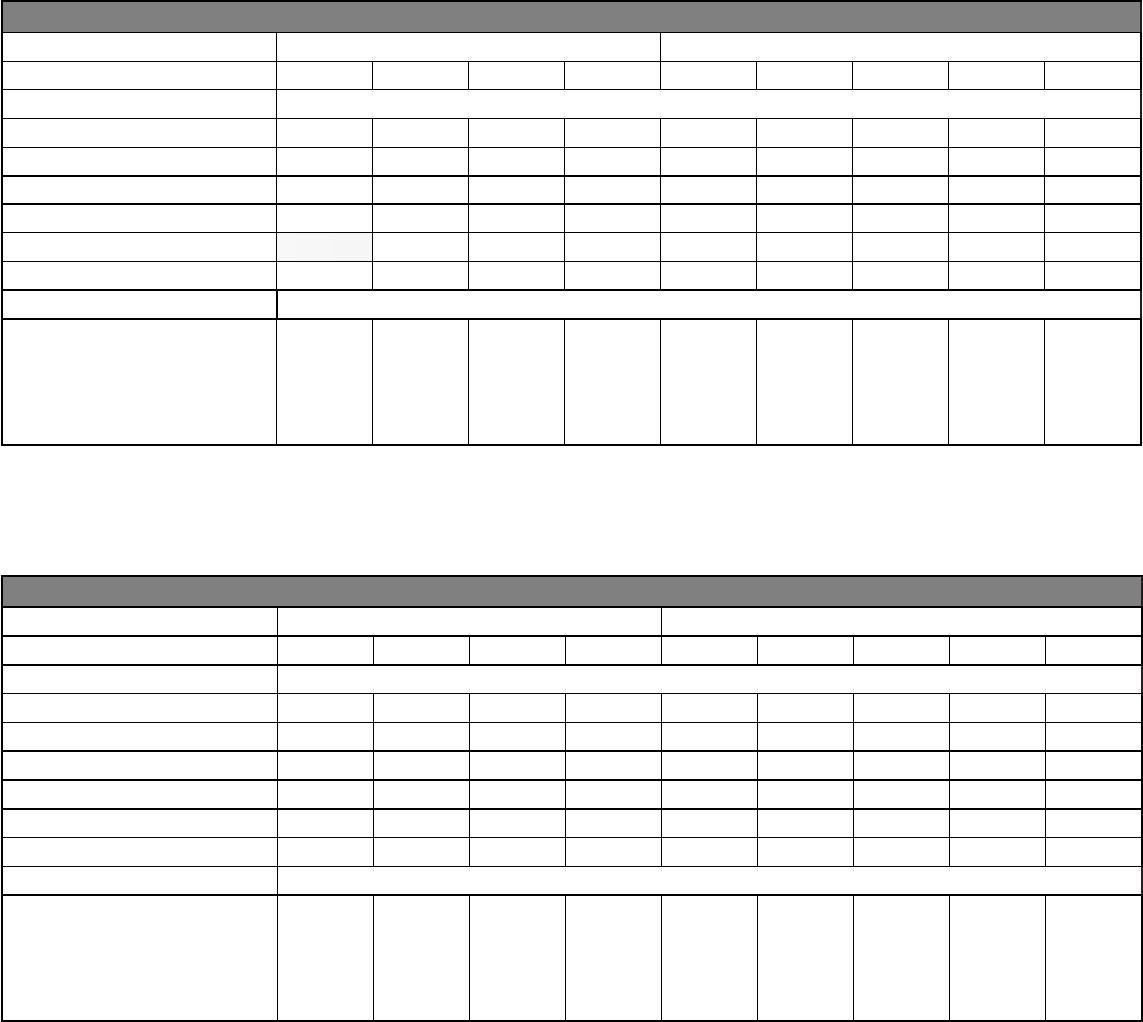
CHASSIS SPECIFICATIONS K-Series models 230/208V, R-Series models 265V
MODEL
VHA09K VHA09R VHA12K VHA12R VHA18K VHA18R VHA24K VHA24R
COOLING DATA
TOTAL COOLING CAP.
9300 9300 11500 11500 18400 18400 22500 22500
SENSIBLE COOL CAP.
7440 7440 9085 9085 13430 13430 15750 15750
POWER (W)
845 845 1045 1045 1670 1670 2045 2045
EER
11.0 11.0 11.0 11.0 11.0 11.0 11.0 11.0
HEATER SIZE (kW)
2.5/3.4/5.0 2.5/3.4/5.0 2.5/3.4/5.0 2.5/3.4/5.0 2.5/3.4/5.0/7.5 2.5/3.4/5.0/7.5 2.5/3.4/5.0/7.5/10.0 2.5/3.4/5.0/7.5/10.0
HEAT PUMP DATA
REVERSE HEATING BTU
8300 8300 10600 10600 16700 16700 19500 19500
COP @ 47F
3.3 3.3 3.3 3.3 3.3 3.3 3.3 3.3
HEATING POWER (W)
730 730 940 940 1480 1480 1732 1732
HEATING CURRENT (A)
3.6 3.1 4.5 3.7 7.0 6.1 9.2 9.2
ELECTRICAL DATA
VOLTAGE (1 PHASE, 60 HZ)
208-230 265 208-230 265 208-230 265 208-230 265
VOLT RANGE
197-253 239-292 197-253 239-292 197-253 239-292 197-253 239-292
COOLING CURRENT (A)
4.1 3.5 4.9 4.0 7.9 7.0 10.5 10.5
AMPS L.R
21.0 21.0 23.0 23.0 37.0 37.0 44.0 44.0
INDOOR MOTOR (HP)
1/4 1/4 1/4 1/4 1/4 1/4 1/5 1/5
INDOOR MOTOR (A)
1.2 1.2 1.2 1.2 0.42 0.42 1.4 1.4
OUTDOOR MOTOR (HP)
— — — — 1/4 1/4 1/4 1/4
OUTDOOR MOTOR (A)
— — — — 1.6 1.6 1.7 1.7
PHYSICAL
DIMENSIONS (W X D X H)
23”x23”x32” 23”x23”x32” 23”x23”x32” 23”x23”x32” 23”x23”x47” 23”x23”x47” 23”x23”x52” 23”x23”x52”
NET WEIGHT (LBS)
142 144 147 149 190 192 225 227
SHIPPING WEIGHT (LBS)
164 166 169 171 216 218 251 253
TEST SETTING
LOW LOW LOW LOW LOW LOW LOW LOW
R410A CHARGE (OZ)
38.0 38.0 42.1 42.1 57.0 57.0 62 62
AIRFLOW DATA
INDOOR CFM
LOW HIGH LOW HIGH LOW HIGH LOW HIGH LOW HIGH LOW HIGH LOW HIGH LOW HIGH
.10” ESP
430 490 430 490 430 490 430 490 630 675 630 675 660 700 660 700
.15” ESP
410 470 410 470 410 470 410 470 595 640 595 640 615 665 615 665
.20” ESP
360 440 360 440 360 440 360 440 550 600 550 600 575 625 575 625
.25” ESP
310 400 310 400 310 400 310 400 505 550 505 550 525 580 525 580
.30” ESP
260 350 260 350 260 350 260 350 455 500 455 500 485 540 485 540
.35" ESP
-
-
-
-
-
-
-
-
400 445 400 445 450 500 450 500
.40" ESP
-
-
-
-
-
-
-
-
345 400 345 400 415 465 415 465
VENT CFM
UP TO " " CFM
60
60
60
60
60
60
60
60
60 60 60 60 60 60 60 60
NOTES:
Cooling Standards: 95°F DB/75°F WB OUTDOOR, 80°F DB/67°F WB INDOOR
Heating Standards: 47°F DB/43°F WB OUTDOOR, 70°F DB/60°F WB INDOOR
Normal Value Wet Coil @ .1” ESP.
Rated CFM at Low Speed: VHA09 - 430 CFM VHA12 - 430 CFM
VHA18 - 630 CFM VHA24 - 655 CFM
Due to continuing research in new energy-saving technology, specications are subject to change without notice.
3
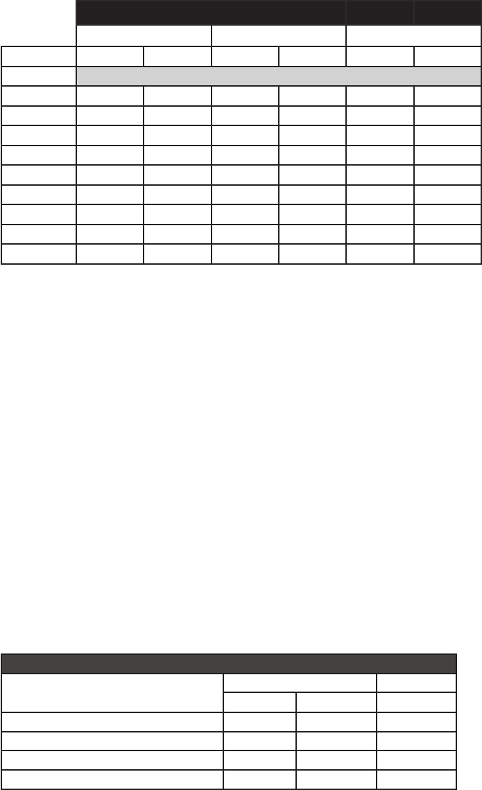
SMALL CHASSIS ELECTRICAL DATA
ELECTRICAL DATA
VHA09K VHA12K
HEATER WATTS 2050-2500 2780-3400 4090-5000 2050-2500 2780-3400 4090-5000
VOLTAGE 208-230
ELECTRIC HEATING BTU 7000-8500 9500-11600 13900-17000 7000-8500 9500-11600 13900-17000
ELEC. HEATING CURRENT (AMPS) 11.5-12.5 15.0-16.4 21.3-23.3 11.5-12.5 15.0-16.4 21.3-23.3
MINIMUM CIRCUIT AMPACITY 16.0 20.9 29.6 16.0 20.9 29.6
BRANCH CIRCUIT FUSE (AMPS) 20 25 30 20 25 30
LRA-COMPRESSOR (AMPS) 21.0 21.0 21.0 23.0 23.0 23.0
BASIC HEATER SIZE 2.5KW 3.4KW 5.0KW 2.5KW 3.4KW 5.0KW
POWER CONNECTION HARD WIRED HARD WIRED
RECOMMENDED BRANCH
CIRCUIT WIRE SIZES
*AWG- AMERICAN WIRE GAUGE
12 12 10 12 12 10
ELECTRICAL DATA
VHA09R VHA12R
HEATER WATTS 2500 3400 5000 2500 3400 5000
VOLTAGE 265
ELECTRIC HEATING BTU 8500 11600 17000 8500 11600 17000
ELEC. HEATING CURRENT (AMPS) 11 14.4 20.5 11 14.4 20.5
MINIMUM CIRCUIT AMPACITY 14.2 18.5 26 14.2 18.5 26
BRANCH CIRCUIT FUSE (AMPS) 15 20 30 15 20 30
LRA-COMPRESSOR (AMPS) 21.0 21.0 21.0 23.0 23.0 23.0
BASIC HEATER SIZE 2.5KW 3.4KW 5.0KW 2.5KW 3.4KW 5.0KW
POWER CONNECTION HARD WIRED HARD WIRED
RECOMMENDED BRANCH
CIRCUIT WIRE SIZES
*AWG- AMERICAN WIRE GAUGE
14 12 10 12 12 10
4
Due to continuing research in new energy-saving technology, specications are subject to change without notice.
LARGE CHASSIS ELECTRICAL DATA
ELECTRICAL DATA
VHA18K VHA24K
HEATER WATTS 2050-2500 2780-3400 4090-5000 6135-7500 2050-2500 2780-3400 4090-5000 6135-7500 8180-10000
VOLTAGE 208-230
ELECTRIC HEATING BTU 7000-8500 9500-11600 13900-17000 20900-25600 7000-8500 9500-11600 13900-17000 20900-25600 27900-34100
ELEC. HEATING CURRENT (AMPS) 11.5-12.5 15.0-16.4 21.3-23.3 31.1-34.2 11.3-12.3 14.8-16.2 21.1-23.1 30.9-34.0 40.7-44.9
MINIMUM CIRCUIT AMPACITY 15.6 20.5 29.2 42.8 15.4 20.3 29.0 42.6 56.1
BRANCH CIRCUIT FUSE (AMPS) 20 25 30 45 20 25 30 45 60
LRA-COMPRESSOR (AMPS) 37.0 37.0 37.0 37.0 44.0 44.0 44.0 44.0 44.0
BASIC HEATER SIZE 2.5KW 3.4KW 5.0KW 7.5KW 2.5KW 3.4KW 5.0KW 7.5K W 10.0KW
POWER CONNECTION HARD WIRED HARD WIRED
RECOMMENDED BRANCH
CIRCUIT WIRE SIZES
*AWG- AMERICAN WIRE GAUGE
12 12 10 6 12 10 10 6 4
ELECTRICAL DATA
VHA18R VHA24R
HEATER WATTS 2500 3400 5000 7500 2500 3400 5000 7500 10000
VOLTAGE 265
ELECTRIC HEATING BTU 8500 11600 17000 25600 8500 11600 17000 25600 34100
ELEC. HEATING CURRENT (AMPS) 10.5 13.9 19.9 29.9 10.8 14.2 20.3 29.7 39.1
MINIMUM CIRCUIT AMPACITY 13.8 18.0 25.7 37.4 13.6 17.8 25.4 37. 2 49.0
BRANCH CIRCUIT FUSE (AMPS) 15 20 30 40 20 20 30 40 50
LRA-COMPRESSOR (AMPS) 37.0 37.0 37.0 37.0 44.0 44.0 44.0 44.0 44.0
BASIC HEATER SIZE 2.5KW 3.4KW 5.0KW 7.5KW 2.5KW 3.4KW 5.0KW 7.5K W 10.0KW
POWER CONNECTION HARD WIRED HARD WIRED
RECOMMENDED BRANCH
CIRCUIT WIRE SIZES
*AWG- AMERICAN WIRE GAUGE
14 12 10 6 12 12 10 6 4
5
AIRFLOW DATA
Indoor CFM & External Static Pressure
Model
VHA09/VHA12 VHA18 VHA24
Fan Speed Low High Low High Low High
ESP (“) SCFM
0.0” 470
520 730 800 755 805
0.05” 460
510 670 735 700 750
0.10” 430
490 630 675 660 700
0.15” 410 470 595 640 615 665
0.20” 360 440 550 600 575 625
0.25”
310
400 505 550 525 580
0.30” 260 350 455 500 485 540
0.35” -- -- 400 445 450 500
0.40” -- -- 345 400 415 465
Indoor air ow may be determined by measuring the external static pressure (ESP) of the duct system using an inclined
manometer or magnahelic gauge and consulting the above chart to derive actual air ow. Under no circumstances
should the small chassis Vert-I-Pak equipment be operated at an external static pressure in excess of 0.3” W.C. on the
VHA09 & VHA12 and 0.4”W.C. on the VHA18 & VHA24. Operation of the Vert-I-Pak under these conditions will result in
inadequate air ow, leading to poor performance and/or premature component failure.
Control
For LOW speed only operation, connect the fan output terminal from the thermostat to the GL terminal of the electronic
control.
For HIGH speed only operation, connect the fan output terminal from the thermostat to the GH terminal of the electronic
control.
For thermostats with two-speed capability, connect the LOW speed output to the GL terminal and the HIGH speed output
to the GH terminal.
NOTE: Any non-Friedrich thermostat of low voltage device being powered by the Vert-I-Pak will need to be reviewed and
approved for use.
Condenser External Static Pressure
Model
Design Maximum
CFM
ESP ("WC) ESP ("WC)
VHA09 650 0.03 0.12
VHA12 650 0.03 0.12
VHA18 950 0.03 0.12
VHA24 980 0.03 0.12
Condenser CFM & External Static Pressure
VPAK is designed to install through an exterior wall with a plenum (VPAWP-8, VPAWP-14) and a Friedrich external louver .
If the Friedrich designed plenum and louver combinations are not used, the selections and design must be evaluated by Friedrich to ensure the
total pressure drop does not exceed the maximum allowable limits.
6
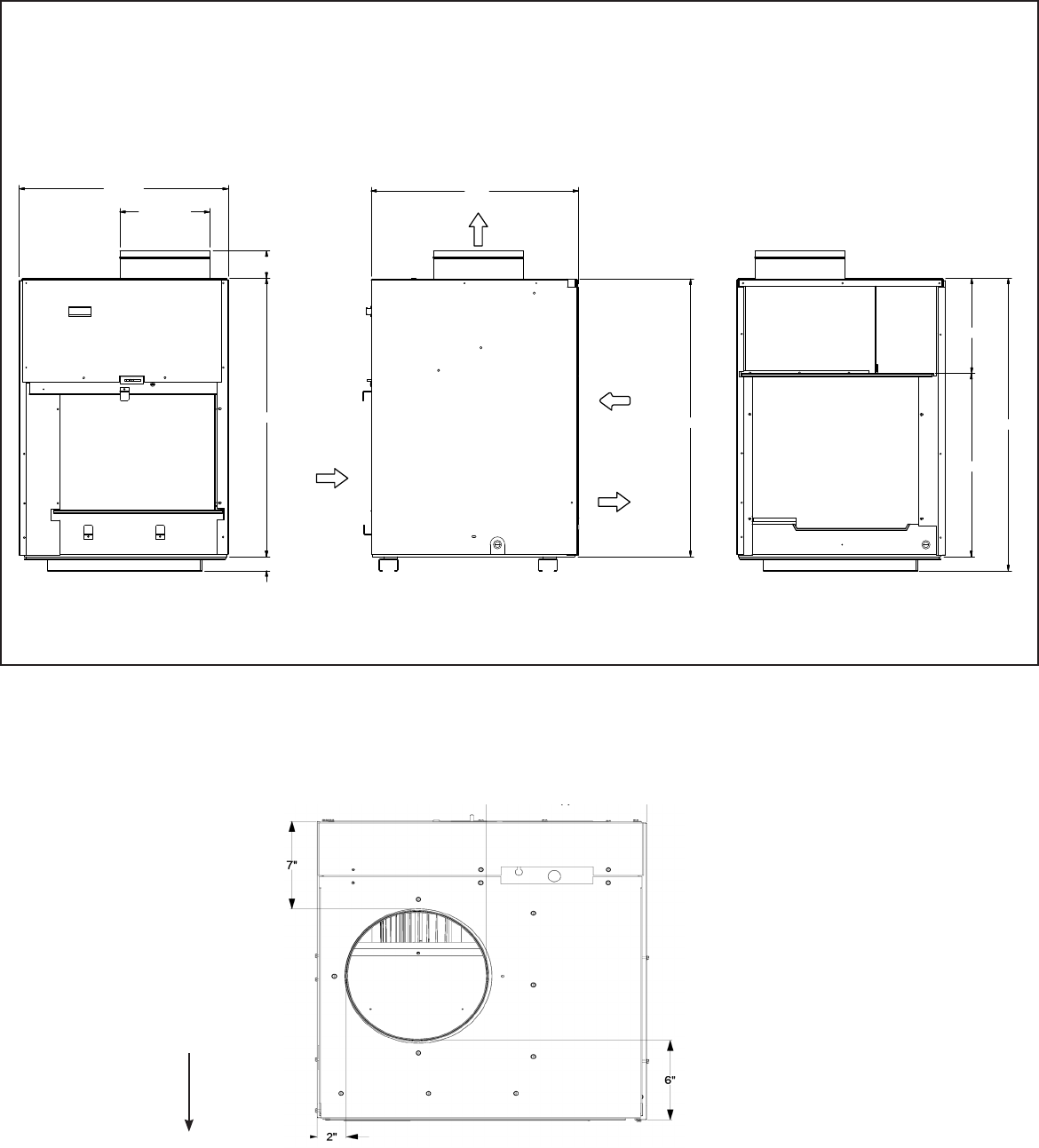
UNIT CHASSIS DIMENSIONS - VHA09 & VHA12
DUCT
DIAMETER
SUPPLY
AIR
CONDENSER
INLET AIR
CONDENSER
EXHAUST
AIR
RETURN
AIR
Front Side Rear
23 1/8”
10”
2 15/16”
29 1/2”
29 1/2”
1 1/2”
23 1/8”
10 1/8”
19 1/2”
31”
Outside Wall
UNIT TOP VIEW DIMENSIONS
7
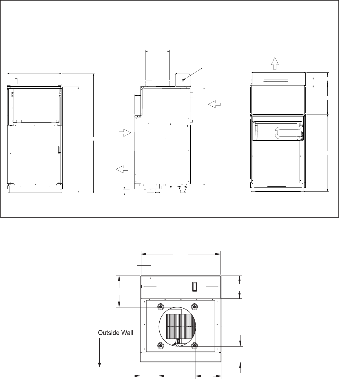
UNIT CHASSIS DIMENSIONS - VHA18
42 5/8”
39 3/4”
2 3/16”
5 1/16”
31”
11 11/16”
47 15/16”
2 1/2
10”
DUCT
DIAMETER
SUPPLY
AIR
RETURN
AIR
CONDENSER
INLET
AIR
ELECTRICAL
ENTRY
BOTH SIDES
CONDENSER
EXHAUST
AIR
FRONT
SIDE
REAR
1 1/2”
Lorem ipsum
UNIT TOP VIEW DIMENSIONS
electrical
entrance
control box
22
5
/
16
"
8
3
/
8
"
6
3
/
16
"
4
3
/
16
"
7
3
/
16
"
5
5
/
16
"
8
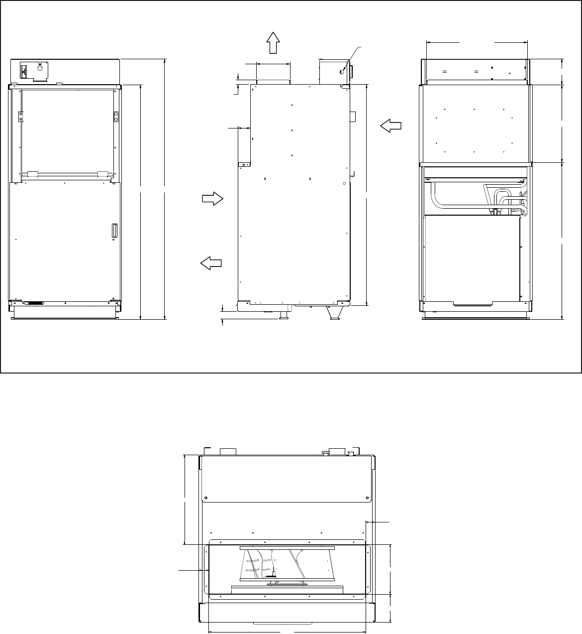
UNIT CHASSIS DIMENSIONS - VHA24
46
11/16"
51 3/4"
1 1/2
"
44
2 1/2
"
CONDENSER
INLET
AIR
CONDENSER
EXHAUST
AIR
FRONT
SIDE
REAR
6 55/64
"
DUCT
1
"
DUCT
ELECTRICAL
ENTRY
BOTH SIDES
RETURN
AIR
15
11
/16
"
3
1"
5
1/6"
20 5/8
"
DUCT
SUPPLY
AIR
UNIT TOP VIEW DIMENSIONS
P
A
R
T
N
O
.
3 55/64
1 1/2
"
12 19/64
"
1 1/2
"
6 55/64
"
20 5/8
"
Outside Wall
9
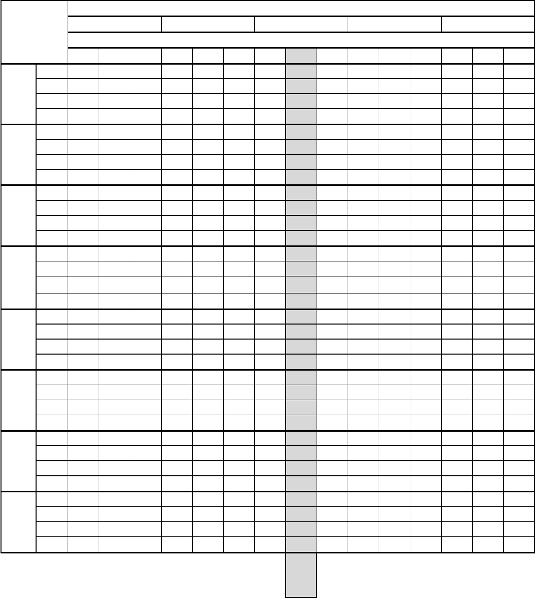
EXTENDED COOLING PERFORMANCE
OUTDOOR DRY BULB TEMP. (DEGREES F AT 40% R.H.)
75 85 95 105 115
INDOOR WET BULB TEMP. (DEGREES F AT 80 F D.B.)
62 67 72 62 67 72 62 67 72 62 67 72 62 67 72
VHA09K
BTUH 9485 10084 10408 8949 9776 10216 8427 9300 9879 7914 8686 9409 7373 7986 8821
WATTS 728 738 745 773 789 798 820 845 858 876 904 923 938 965 991
AMPS 3.6 3.6 3.6 3.7 3.8 3.8 4.0 4.1 4.2 4.3 4.4 4.5 4.6 4.7 4.8
SHR 0.99 0.73 0.55 1.00 0.77 0.56 1.00 0.80 0.57 1.00 0.83 0.58 1.00 0.87 0.60
VHA12K
BTUH 11608 12169 12488 11218 11916 12319 10763 11500 11975 10304 10962 11476 9785 10339 10847
WATTS 877 886 893 953 970 979 1023 1045 1059 1092 1114 1132 1158 1178 1199
AMPS 4.1 4.2 4.2 4.5 4.5 4.6 4.8 4.9 5.0 5.1 5.2 5.3 5.4 5.5 5.6
SHR 0.99 0.74 0.55 1.00 0.77 0.56 1.00 0.79 0.57 1.00 0.81 0.58 1.00 0.84 0.58
VHA18K
BTUH 18512 19518 20299 17915 19060 19912 17107 18400 19319 16156 17583 18552 15187 16641 17641
WATTS 1401 1423 1446 1520 1552 1580 1624 1673 1704 1719 1786 1824 1819 1893 1938
AMPS 6.6 6.7 6.8 7.2 7.3 7.5 7.7 7.9 8.0 8.1 8.4 8.6 8.6 8.9 9.2
SHR 0.91 0.70 0.52 0.94 0.71 0.53 0.96 0.73 0.54 1.00 0.75 0.54 1.00 0.77 0.55
VHA24K
BTUH 23555 24762 25388 22096 23348 24301 21020 22500 23530 19830 21403 22745 19051 20337 21225
WATTS 1824 1866 1921 1963 2003 2048 2005 2045 2072 2021 2092 2140 2228 2311 2357
AMPS 9 9.2 9.4 9.6 9.8 10 10.2 10.5 10.7 10.7 11.1 11.3 11.4 11.8 12.1
SHR 0.87 0.66 0.49 0.88 0.68 0.5 0.91 0.7 0.51 0.96 0.72 0.5 0.99 0.75 0.5
VHA09R
BTUH 9485 10084 10408 8949 9776 10216 8427 9300 9879 7914 8686 9409 7373 7986 8821
WATTS 728 738 745 773 789 798 820 845 858 876 904 923 938 965 991
AMPS 3.1 3.1 3.1 3.2 3.3 3.3 3.5 3.5 3.6 3.7 3.8 3.9 4.0 4.1 4.2
SHR 0.99 0.73 0.55 1.00 0.77 0.56 1.00 0.80 0.57 1.00 0.83 0.58 1.00 0.87 0.60
VHA12R
BTUH 11608 12169 12488 11218 11916 12319 10763 11500 11975 10304 10962 11476 9785 10339 10847
WATTS 877 886 893 953 970 979 1023 1045 1059 1092 1114 1132 1158 1178 1199
AMPS 3.4 3.4 3.4 3.6 3.7 3.7 3.9 4.0 4.1 4.2 4.3 4.3 4.4 4.5 4.6
SHR 0.99 0.74 0.55 1.00 0.77 0.56 1.00 0.79 0.57 1.00 0.81 0.58 1.00 0.84 0.58
VHA18R
BTUH 18512 19518 20299 17915 19060 19912 17107 18400 19319 16156 17583 18552 15187 16641 17641
WATTS 1401 1423 1446 1520 1552 1580 1624 1673 1704 1719 1786 1824 1819 1893 1938
AMPS 5.9 6 6.1 6.4 6.5 6.6 6.8 7.0 7.1 7.2 7.5 7.6 7.6 7.9 8.1
SHR 0.91 0.70 0.52 0.94 0.71 0.53 0.96 0.73 0.54 1.00 0.75 0.54 1.00 0.77 0.55
VHA24R
BTUH 23555 24762 25388 22096 23348 24301 21020 22500 23530 19830 21403 22745 19051 20337 21225
WATTS 1824 1866 1921 1963 2003 2048 2005 2045 2072 2021 2092 2140 2228 2311 2357
AMPS 9 9.2 9.4 9.6 9.8 10 10.2 10.5 10.7 10.7 11.1 11.3 11.4 11.8 12.1
SHR 0.87 0.66 0.49 0.88 0.68 0.5 0.91 0.7 0.51 0.96 0.72 0.5 0.99 0.75 0.5
RATING
POINT
AHRI
390
10
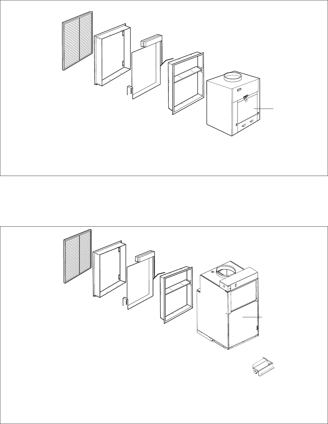
INSTALLATION OVERVIEW
VHA09 & VHA12
Louver VPAL2/VPSC2
(Sold separately)
Exterior/
Outside Wall
Part B
Inside
Wall Plenum
Unit
Part A
Outside
Wall Plenum
Applicable Models
VHA09K
VHA09R
VHA12K
VHA12R
Filter (14” x 20”)
Louver VPAL2/VPSC2
(Sold separately)
Exterior/
Outside Wall
Part B
Inside
Wall Plenum
Part A
Outside
Wall Plenum
Large Chassis Unit
(Unit height 47”)
VPDP2 drain pan required
(Sold & shipped
separately)
Filter (14” x 20”)
VPAWP1-8 = 5 1/2" - 8" D x 24 1/8" W x 30 3/8" H
VPAWP1-14 = 8" - 14" D x 24 1/8" W x 30 3/8" H
INSTALLATION OVERVIEW
VHA18
VPAWP1-8 = 5 1/2" - 8" D x 24 1/8" W x 30 3/8" H
VPAWP1-14 = 8" - 14" D x 24 1/8" W x 30 3/8" H
Applicable Models
VHA18K
VHA18R
11
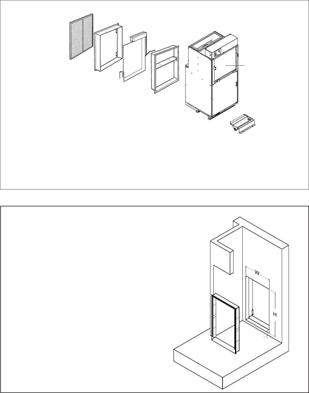
INSTALLATION OVERVIEW
VHA24
Louver VPAL2/VPSC2
(Sold separately)
Exterior/
Outside Wall
Part B
Inside
Wall Plenum
Unit
Part A
Outside
Wall Plenum
Applicable Models
VHA24K
VHA24R
Filter (18” x 20”)
VPAWP1-8 = 5 1/2" - 8" D x 24 1/8" W x 30 3/8" H
VPAWP1-14 = 8" - 14" D x 24 1/8" W x 30 3/8" H
VPDP2 drain pan required
(Sold & shipped
separately)
3/4”
NOTE: The distance between the rough
opening and the nished oor/platform
must be 3/4”.
INSTALL HEIGHT
12
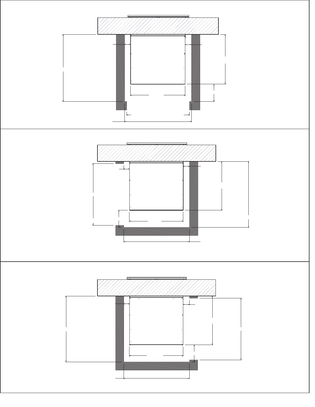
INSTALLATION OVERVIEW
CLOSET ORIENTATIONS AND DIMENSIONS
)URQW,QVWDOODWLRQ7RS9LHZ
/HIW,QVWDOODWLRQ7RS9LHZ
5LJKW,QVWDOODWLRQ7RS9LHZ
3
23 1/8"
23 1/8"
23 1/8"
23 1/8"
23 1/8"
23 1/8"
31 1/8"
31 1/8"
30 5/8"
30 5/8"
3"
26 1/8"
29 1/8"
27"
27"
27"
13
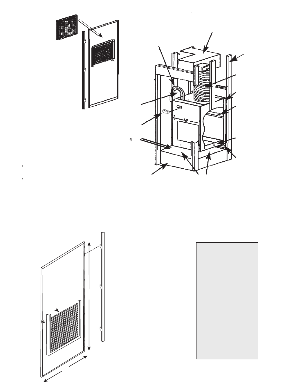
TYPICAL UTILITY CLOSET
58"
29"
Cutout
Dimensions:
27" W x 55-
3
⁄
4
" H
Hinge on left
Side of door
Same indoor (closet) wall cut
out for all models
VPRG4/VPRG4R
Access Panel and
Return Air Filter Grille
Electrical
Connection
Rigid Ductwork
Flexible Ductwork
Exterior Wall
V PAW P1 - 8 /1-14
Wall Plenum
Plenum Divider
3/4" FPT Drain
Connection
Optional, field-supplied platform
Please reference orientation details
for clearance requirements
Power
Disconnect
Wiring
Chassis installs
2
3
/
8
" into Plenum
V PAW P1-8/1-14 WallPlenum cut-out
dimensions 24
5
/
8
" wide x 30
7
/
8
" high.
VPRG4 Access Panel cutout dimensions:
27"wideby55
3
/
4
" high.
Recommended eld
installed drain pan
25" x 20" Filter
(Field Supplied)
Thermostat
Chassis shown in closet on
optional platform
Access Panel with
Return Air Grille
VPRG4/VPRG4R
Filter Size: 25” x 20”
Field Supplied
14
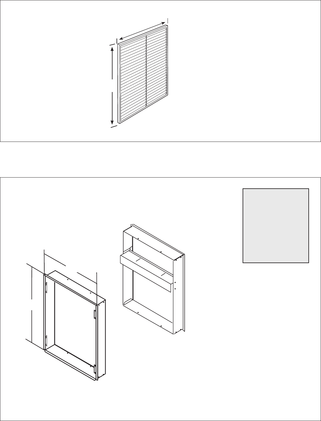
ACCESSORIES DIMENSIONS
VPAL2 / VPSC2 Louver
VPAWP1-8 Wall Plenum
Cutout
Dimensions:
24-
5
/
8
" W x 30-
7
⁄
8
”H
Architectural Louver
VPAL2/VPSC2
25-
9
/
16
”
31-
1
/
16
”
Wall Plenum
VPAWP1-8 - telescopes from 5-
1
/
2
” to 8”
VPAWP1-14 - telescopes from 8” to 14”
A
B
30-
3
/
8
"
24-
1
/
8
"
15
Application and Accessories (All models)
• The use of a Friedrich wall plenum is required for instal-
lation. Plenum opening is
3
/
4
" above the oor (VPAWP1-8 /
VPAWP1-14).
• Return air is accommodated with a return air lter attached
to the unit or through the use of a return air lter grille.
(VPRG4/VPRG4R).
• Exterior louvers are available in anodized aluminum (VPAL2)
or in custom painted colors (VPSC2).
• Unit is controlled by a remote wall-mounted thermostat.
Friedrich model WRT2 wireless digital thermostat, RT7
wired digital thermostat, RT7P wired programmable ther-
mostat, or EMRT2/EMWRT2 Energy Management Stats are
recommended.
• Central desk control ready.
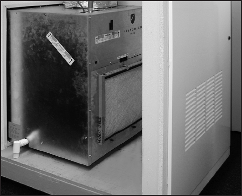
Typical Closet Arrangement
Cutaway of a typical closet shown with Vert-I-Pak
®
chassis
installed in the wall sleeve. The unit has the thermostat, eld
wiring, internal drain and ex duct attached. VPRG4 return air
lter holder and access panel are shown below.
The closet access panel may be installed in the front (as shown
below) or to the left or right side of the unit. All three installation
options will allow easy access to the unit for removal and
replacement.
Application and Installation
Installation Guidelines
• Chassis is to be installed against an exterior wall. Wall
cutout dimensions will be 24 5/8" w x 30 7/8" h.
• Closet should allow for a minimum of three inches on three
sides of the unit for return air, drain connections and change
outs.
• Minimum recommended access door rough-in measure-
ments 27" wide by 55
3
/
4
" high (for VPRG4/VPRG4R).
• Friedrich recommends the use of a platform between 24"
and 36" above the oor, for ease of installation and ser vice-
ability.
• Duct outlet designed for external static pressures up to .3"
on 9,000 and 12,000, Btu models
• Duct outlet designed for external static pressures up to .4"
on 18,000 and 24,000, Btu models
• Wall plenum allows chassis to be inserted 2
3
/
8
" into ple-
num, thereby minimizing closet dimensions.
• Quick connect drain coupling ships standard to make
installation and removal easier.
Application and Accessories (18K & 24K Models)
• 18K & 24K utilize a drain pan (VPDP2) that can be installed
prior to chassis for simplied installation and removal.
16
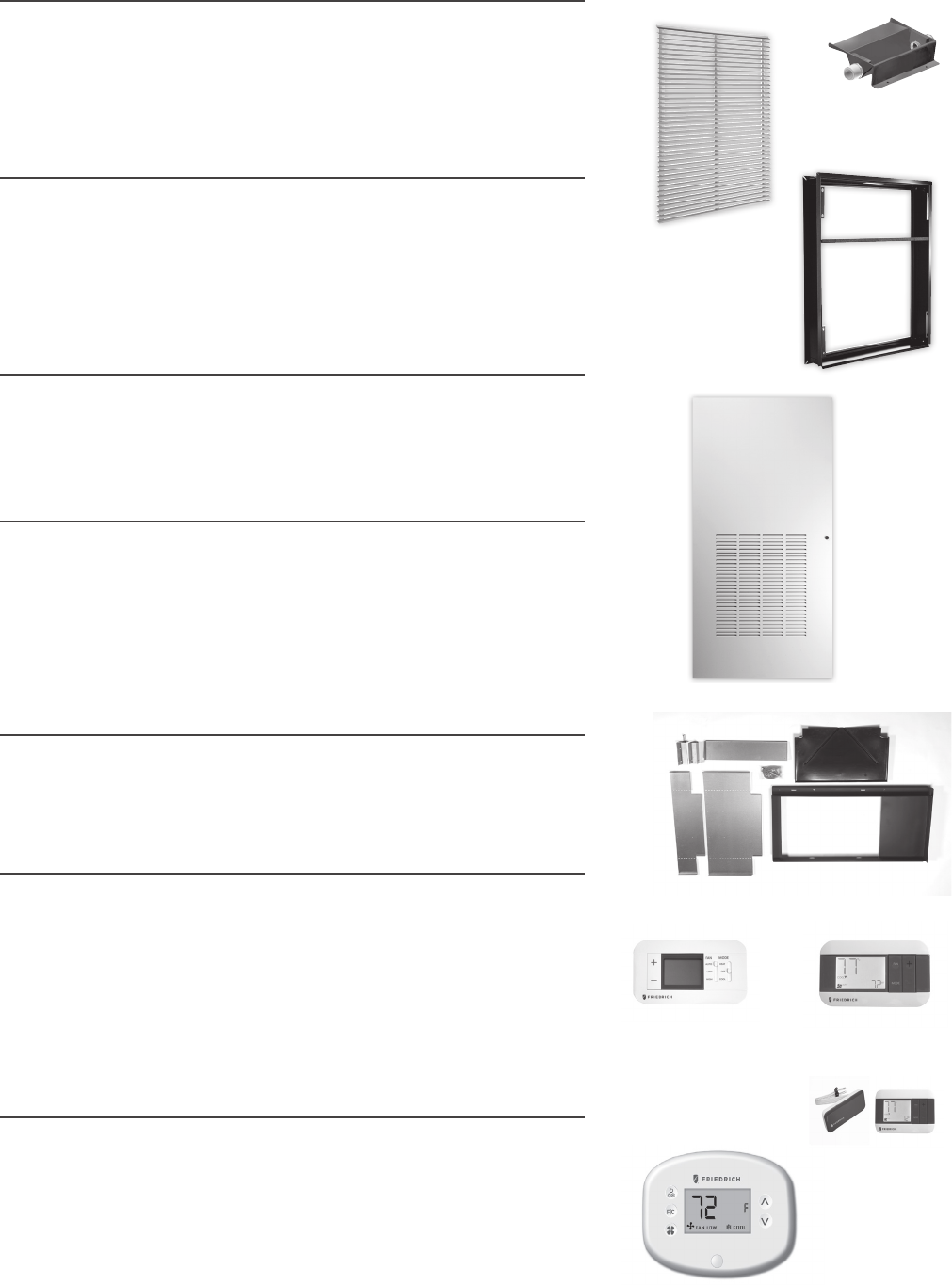
REQUIRED ACCESSORIES
ARCHITECTURAL LOUVER
VPAL2 and VPSC2
Extruded aluminum grille that attaches to the outdoor section of the wall
plenum. Takes in fresh air and returns condensed air. VPSC2 can be ordered in
custom colors.
DIMENSIONS: 25 9/16" W x 31 1/16" H
WALL PLENUM
VPAWP1-8, VPAWP1-14
Two-part sleeve that telescopes in and out. Sits inside the exterior wall
penetration.
VPAWP1-8 telescopes from 5 1/2”–8”
VPAWP1-14 telescopes from 8”–14”
DIMENSIONS: 24 1/8” W x 30 3/8” H
CUTOUT DIMENSIONS: 24 5/8” W x 30 7/8” H
DRAIN PAN
VPDP2
Required for all VHA18 and VHA24 models. May be installed prior to chassis for easy
installation/removal.
RETURN AIR GRILLE/ACCESS PANEL
VPRG4 / VPRG4R
Hinged panel allows access to unit and return air lter.
A eld-supplied lter (25” x 20”) should be mounted on the inside grille. Panel
can be mounted with return air openings high or low on the door for optimum
sound attenuation.
DIMENSIONS: 29” W x 58” H
CUTOUT DIMENSIONS: 27” W x 55 3/4” H
FIRST COMPANY SLEEVE ADAPTER
VPASA1
Single piece, welded adapter allows retrot into existing First Company SPXR-
series single package vertical unit wall sleeve and louver. Easy connection to
Friedrich small chassis VERT-I-PAK.
SINGLE STAGE THERMOSTATS
RT7P
Wired, single stage, wall-mounted programmable thermostat has two fan
speeds and backlight. Controls Friedrich VERT-I-PAK.
RT7
Wired, single stage, wall-mounted digital thermostat with two fan speeds and
backlight for control of Friedrich VERT-I-PAK.
WRT2
Wireless, single stage, wall-mounted digital thermostat with two fan speeds
and backlight for control of Friedrich VERT-I-PAK.
ENERGY MANAGEMENT THERMOSTATS
EMRT2/EMWRT2
Wired/Wireless thermostat with occupancy sensor.
EMOCT EMRAF EMROS
Online connection kit. Remote access fee. Remote Occupancy Sensor
EMRTS EMRDS EMCWP EMRWOS
Remote Temperature Sensor Door Switch Wall-Plate Wireless Occ. Sensor
RT7
EMRT2, EMWRT2
VPAL2
VPAWP1-8/14
VPRG4/R
VPASA1
VPDP2
RT7
WRT2
OPTIONAL ACCESSORIES
17
All units shall be factory assembled, piped, wired and fully
charged with R-410A. All units shall be certied in accordance
with ARI Standard 390 for Single Packaged Vertical Air Condi-
tioners and Heat Pumps. Units shall be ETL listed and carry a
ETL label. All units shall be factory run-tested to check opera-
tion and be manufactured by Friedrich or equivalent.
The basic unit shall not exceed 23
1
/
8
" wide x 23
1
/
8
" deep. Overall
height of the unit from the bottom of the isolators to the top of
the duct collar shall not exceed 32 ¼" for models up to 12,000
Btu , 47 ¼" for 18,000 Btu models, and 51 1/4" for 24,000 Btu
models. The unit shall be designed so that the unit will insert
into a factory supplied wall plenum 2
3
/
8
" to minimize room intru-
sion. Factory supplied wall plenums shall allow for installation
through walls from 4 ½" – 14" in thickness. Wall plenums will be
adjustable to minimize installation clearances. Unit shall draw
in ambient air through upper portion of an outside architectural
louver measuring 25
9
/
16
" wide x 31
1
/
16
" high and shall exhaust
heated air out through the lower portion of the louver. The unit
shall be secured to the architectural louver by means of a two
part, weather-resistant wall plenum. The unit shall be capable
of left, right or straight-in installations into mechanical closet
without eld modications.
REFRIGERATION SYSTEM – The refrigeration system shall be her-
metically sealed and consist of a rotary compressor that is exter-
nally mounted on vibration isolators no smaller than 1 ¾" dia. x 1 ½"
high; condenser and evaporator coils constructed of copper tubes
and aluminum plate ns; and capillaries as expansion devices. Unit
shall have a fan slinger ring to increase efciency and condensate
disposal. A primary condensate removal system consisting of ¾"
FTP ttings on multiple locations shall exist. A secondar y over ow
from the primary drain pan shall expel water to the outside of the
building through the wall plenum and louver in the event that the
primary drain line clogs.
AIR HANDLING SECTION – The condenser fan shall be driven
by a single BLDC fan motor for models up to 12,000 Btu. 18,000
and 24,000 Btu models shall utilize a separate motor for both
the indoor and outdoor air sections. Airow shall be directed
ver tically up through a standard 10" ex duct starter collar and
into exible or rigid ducts to be distributed into the conditioned
area on models up to 18,000 Btu. Starter collar shall have both
crimped edge to ease ex duct installation and a waistline to
prevent duct from loosening.
The chassis shall have a built-in damper capable of providing
up to 60 CFM of fresh air into the conditioned area. A ne mesh
screen shall lter the incoming fresh air. The damper can be
controlled by a slide lever located on the front of the unit.
CONTROLS – The unit shall be factory equipped with terminal
strip for connection to a standard 24-volt single-stage heat/
cool thermostat. A transformer shall be included and fac-
tory wired to work with Friedrich branded or factory approved
devices.. Low voltage inputs will include: C (common), R (24V
power), Y (cooling), G (fan), W (heat) and B (reversing valve on
VHA heat pumps only).The unit shall be hard-wired and have
a quick-disconnect to disable power for control box service.
An emergency heat override switch must be available to allow
operation of the resistance heater in the event of a compressor
failure on heat pump models.
GENERAL CONSTRUCTION – The unit shall be constructed of
18-gauge galvanized zinc-coated steel. The unit shall feature
½" foil backed insulation for sound and thermal efciency.
The wall plenum (required factory accessory) shall be shipped
separately and constructed of 20-gauge galvanized zinc-coated
steel; pretreated with zinc-phosphate and sealed with a chro-
mate rinse, then powder-coated for maximum coverage and
protection. The plenum shall be black in color for minimal
visibility of unit from exterior of building. The plenum shall be
shipped with a protective weatherboard for use prior to nal
installation of the louver and chassis.
The architectural louver (required factory accessory) shall
be shipped separately and fabricated from extruded anodized
aluminum with louvers in the horizontal plane.
The unit shall include vibration isolators mounted under the
chassis and a nonrigid plenum-to-chassis connection to isolate
vibrations to the building.
The unit shall have a plastic fan, fan shroud and drain pan and
aluminum outdoor coil endplates for corrosion protection and to
help prevent rust on the side of the building below the outdoor
louver.
The unit shall be shipped with return air lter brackets and a
14" x 20" or 18" x 20" lter afxed directly on to the unit chassis.
Optional return air grilles and access panels shall be available
as factory accessories for installation in the wall or door of the
mechanical closet.
CORROSION PROTECTION - The unit shall feature corrosion
-resistant materials and nish to help prevent deterioration.
The outdoor coil shall have Diamonblue advanced corrosion pro-
tection consisting of hydrophilic-coated ns to prolong the life of
the coil in all applications including seacoast protection.
ACCESSORY ACCESS PANEL - An optional factory-supplied access
panel shall be available to provide access to the unit and adequate
return air. The panel shall feature a lter holder to accept a eld
supplied 25” x 20” x 1” lter. Kit shall contain a hinge bracket for
mounting the door with the return air openings high or low on the
door for optimal sound attenuation.
WARRANTY – The warranty is one year on all parts and labor
and 5 years on the sealed system, parts and labor, including
compressor, indoor and outdoor coils and refrigerant tubing.
HVAC Engineering Specications
A-Series Vertical Packaged Air Conditioners & Heat Pumps
Cooling: 9300 – 22500 Btu
Heating: 8300 – 19500 Btu (Heat Pump)
8500 – 34130 Btu (Electric Heat)
Friedrich Models: VHA – Heat Pump with electric heat
18
Vert-I-Pak
®
Single Package Heat Pumps
MODEL IDENTIFICATION GUIDE
Electric Heater Size
A Series
25 = 2.5 KW
34 = 3.4 KW
50 = 5.0 KW
75 = 7.5 KW*
10 = 10.0KW**
MODEL NUMBER V H A 09 K 34 RT P
Marketing Model
Options
RT = Standard Remote Operation
Voltage
K = 208/230V-1Ph-60Hz
R = 265V-1Ph-60Hz
Nominal Capacity
A Series (Btu)
09 = 9,000 18 = 18,000
12 = 12,000 24 = 24,000
Series
VHA=Vertical Heat Pump
* ONLY AVAILABLE ON THE 18 & 24 K/R MODELS
**ONLY AVAILABLE ON THE 24 K/R MODELS
PURCHASER P.O. # DATE
PROJECT LOCATION
ENGINEER ARCHITECT
SUBMITTED BY FOR APPROVAL FOR REFERENCE
ITEM PLAN DESIGNATION QUANTITY COOLING Btu VOLTAGE FRIEDRICH MODEL
A-SERIES ACCESSORIES (Wall Plenum and Outdoor Louver are required)
VPAWP1-8 Adjustable Wall Plenum (5 ½"- 8") Qty
VPAWP1-14 Adjustable Wall Plenum (8"-14") Qty
VPAL2 Architectural Louver Qty
VPSC2 Architectural Louver (color matched) Qty
VPASA1 Sleeve adapter for exact t in existing
First Company SPXR-series with small chas-
sis VPAK
Qty
VPRG4 Return Air Grille/Access Panel Qty
VPRG4R Access Panel (Right In-swing) Qty
VPDP2 Drain Pan for VHA18 & VHA24 Qty
RT7 Wired Digital Wall Thermostat Qty
RT7P Wired Programmable Wall Thermostat Qty
WRT2 Wireless Digital Wall Thermostat Qty
EMRT2 Wired Thermostat with Occupancy Sensor Qty
EMWRT2 Wireless Thermostat with Occupancy
Sensor
Qty
EMOCT Online Connection Kit Qty
EMRAF Remote Access Fee Qty
Qty
Qty
VERT-I-PAK
®
SUBMITTAL_2022

19
SAVE THIS CERTIFICATE. It gives you specic rights. You may also have other rights which may vary from state to state and province to province.
In the event that your unit needs servicing, contact your nearest authorized service center. If you do not know the nearest service center, ask the com-
pany that installed your unit or contact use - see address and telephone number above. To obtain service and/or warranty parts replacement, you must
notify an authorized FRIEDRICH Air Conditioning Co. service center, distributor, dealer, or contractor of any defect within the applicable warranty period.
When requesting service: please have the model and serial number from your unit readily available.
Unless specied otherwise herein, the following applies:
FRIEDRICH VERT-I-PAK A SERIES HEAT PUMPS & AIR CONDITIONERS
LIMITED WARRANTY - FIRST YEAR (Twelve (12) months from the date of installation). Any part found to be defective in the material or workman-
ship will be repaired or replaced free of charge by our authorized service center during the normal working hours; and
LIMITED WARRANTY - SECOND THROUGH FIFTH YEAR (Sixty (60) months from the date of installation). ON THE SEALED REFRIGERATION
SYSTEM. Any part of the sealed refrigeration system that is defective in material or workmanship will be repaired or replaced free of charge (excluding
freight charges) by our authorized service center during normal working hours. The sealed refrigeration system consists of the compressor, metering
device, evaporator, condenser, reversing valve, check valve, and the interconnecting tubing.
These warranties apply only while the unit remains at the original site and only to units installed inside the continental United States, Alaska,
Hawaii, Puerto Rico, Mexico and Canada. The warranty applies only if the unit is installed and operated in accordance with the printed instruc-
tions and in compliance with applicable local installation and building codes and good trade practices. For international warranty information,
contact the Friedrich Air Conditioning Company - International Division.
Any defective part to be replaced must be made available to FRIEDRICH in exchange for the replacement part. Reasonable proof must be presented to
establish the date of install, otherwise the beginning date of this certicate will be considered to be our shipment date plus sixty days. Replacement parts
can be new or re-manufactured. Replacement parts and labor are only warranted for any unused portion of the unit’s warranty.
We will not be responsible for and the user will pay for:
1. Service calls to:
A) Instruct on unit operation. B) Replace fuses or correct wiring. C) Clean or replace air lters. D) Remove the unit from
its installed location when not accessible for service required. E) Correct improper installations.
2. Parts or labor provided by anyone other than an authorized service center.
3. Damage caused by:
A) Accident, abuse, negligence, misuse, riot, re ood or acts of God. B) Operating the unit where there is a corrosive atmosphere containing
chlorine, uorine, or any damaging chemicals (other than in a normal living environment). C) Unauthorized alteration or repair of the unit,
which in turn aects its stability or performance. D) Failing to provide proper maintenance and service. E) Using and incorrect power source. F)
Faulty installation or application of the unit. G) Operation of the unit during construction.
We shall not be liable for any incidental, consequential, or special damages or expenses in connection with any use or failure of this unit. We
have not made and do not make any representation or warranty of tness for a particular use or purpose and there is no implied condition of
tness for a particular use or purpose. We make no expressed warranties except as stated in this certication No one is authorized to change
this certicate or to create for us any other obligation or liability in connection with this unit. Any implied warranties shall last for one year
after the original purchase date. Some states and provinces do not allow limitations on how long an implied warranty or condition lasts, so the above
limitation or exclusions may not apply to you. The provisions of this warranty are in addition to and not a modication of or subtraction from the statutory
warranties and other rights and remedies provided by law.
Performance of Friedrich’s Warranty obligation is limited to one of the following methods:
1. Repair of the unit
2. A refund to the customer for the prorated value of the unit based upon the remaining warranty period of the unit.
3. Providing a replacement unit of equal value
The method of fulllment of the warranty obligation is at the sole discretion of Friedrich Air Conditioning.
In case of any questions regarding the provisions of this warranty, the English version will govern.
(11-19)
VERT-I-PAK
®
SINGLE PACKAGE VERTICAL AIR CONDITIONERS
LIMITED WARRANTY
Friedrich Air Conditioning Company
10001 Reunion Place, Suite 500
San Antonio, Tx 78216
800.541.6645
www.friedrich.com

Friedrich Air Conditioning Co. l 10001 Reunion Place, Suite 500 l San Antonio, TX 78216 l 877.599.5665 l www.friedrich.com
VPAK PP FEB-2023 9521 4200_13
