
PTAC - R410A Models
Packaged Terminal Air Conditioners
Packaged Terminal Heat Pumps
PD-ServMan-E (2-11)
Service Manual
2 0 1 1

FRIEDRICH AIR CONDITIONING CO.
10001 Reunion Place, Ste. 500, San Antonio, TX 78216
(210) 546-0500 877-599-5665 x 261 FAX (210) 546-0630
Email: [email protected]
www.friedrich.com
Printed in the U.S.A.
TECHNICAL SUPPORT
CONTACT INFORMATION
FRIEDRICH AUTHORIZED PARTS DEPOTS
AAA Refrigeration Service
1322 24th Street, Suite B
Kenner, Louisiana 70062
504-464-7444
877-813-7444
Alamo Service Company
1450 North Flores Street
San Antonio, Texas 78212
210-227-2450
800-328-2450
The Gabbert Company
6868 Ardmore
Houston, Texas 77054
713-747-4110
800-458-4110
Johnstone Supply of Woodside
27-01 Brooklyn Queens Expway
Woodside, New York 11377
718-545-5464
800-431-1143
Reeve Air Conditioning, Inc.
2501 South Park Road
Hallandale, Florida 33009
954-962-0252
800-962-3383
CUSTOMER SATISFACTION and QUALITY ASSURANCE
Friedrich is a conscientious manufacturer, concerned about customer satisfaction, product quality, and
controlling warranty costs. As an Authorized Service Provider you play a vital role in these areas. By adhering
to the policies and procedures you provide us with vital information on each warranty repair you complete.
This information is used to identify product failure trends, initiate corrective action, and improve product
quality, thereby further reducing warranty expenses while increasing customer satisfaction levels.
CHARGES TO CUSTOMER
The customer/end user is not to be charged for any warranty repairs to correct defects in materials or
workmanship in accordance with the specifi c warranty provisions outlined in the product’s warranty
certifi cate.
1
Table of Contents
Important Safety Information ...........................................2-4
Introduction .........................................................................4
General Product Features ..................................................5
HVAC Engineering Specifi cations ......................................6
Component identifi cation ....................................................7
Accessories .....................................................................8-9
Unit Identifi cation ..............................................................10
Chassis Specifi cations ......................................................11
Cooling and Heating Performance ..............................12-13
Electric Heat Data ............................................................14
Electrical Rating Tables ....................................................15
Power Cord Information ..............................................15-17
Remote Wall Thermostat / Low Voltage
Wire Connections ........................................................18-19
Digital Control Features ....................................................20
Digital Control Operation ..................................................21
Digital Control User Input Confi guration ...........................22
Digital Control Diagnostics ................................................23
Malfunction Analysis ....................................................24-26
Components Testing ....................................................27-28
Refrigeration System Sequence of Operation ...................29
Sealed Refrigeration System Repairs ...............................30
Refrigerant Charging .........................................................31
Method Of Charging ..........................................................31
Undercharged Refrigerant Systems .............................31-32
Overcharged Refrigerant Systems ....................................32
Restricted Refrigerant Systems .........................................32
Capillary Tube Systems/Check Valve ..........................33
Reversing Valve — Description/Operation ...................34
Testing Coil ...................................................................34
Checking Reversing Valves .....................................34-35
Reversing Valve
Touch Testing Heating/Cooling Cycle ..........................35
Procedure For Changing Reversing Valve ..............35-36
Compressor Checks .....................................................36
Locked Rotor Voltage Test ............................................36
Single Phase Connections ............................................36
Determine Locked Rotor Voltage ..................................36
Locked Rotor Amperage Test ........................................36
Single Phase Running & Locked Rotor Amperage ........36
Checking the Overload ..................................................36
External Overload ..........................................................37
Compressor Single Phase Resistance Test ...................37
Compressor Replacement ........................................38-39
Routine Maintenance .....................................................39
Troubleshooting Charts .............................................40-41
Wiring Diagrams for Wall Mounted Thermostats .......42-43
Wiring Diagram .........................................................42-44
RT6 Installation, Operation and Application Guide ...45-46
Thermistors Resistance Values ................................47-48
Warranty ..........
.....................................................................49
2011 PTAC Exploded View ..........
.....................................50
2011 PTAC Parts List - PDE Models ...
.............................51
2011 PTAC Parts List - PDH Models ...
.............................52
IMPORTANT SAFETY INFORMATION
The information contained in this manual is intended for use by a qualifi ed service technician who is familiar
with the safety procedures required for installation and repair, and who is equipped with the proper tools and
test instruments required to service this product.
Installation or repairs made by unqualifi ed persons can result in subjecting the unqualifi ed person making
such repairs as well as the persons being served by the equipment to hazards resulting in injury or electrical
shock which can be serious or even fatal.
Safety warnings have been placed throughout this manual to alert you to potential hazards that may be
encountered. If you install or perform service on equipment, it is your responsibility to read and obey these
warnings to guard against any bodily injury or property damage which may result to you or others.
Your safety and the safety of others are very important.
We have provided many important safety messages in this manual and on your appliance. Always read
and obey all safety messages.
All safety messages will tell you what the potential hazard is, tell you how to reduce the chance of injury,
and tell you what will happen if the instructions are not followed.
This is a safety Alert symbol.
This symbol alerts you to potential hazards that can kill or hurt you and others.
All safety messages will follow the safety alert symbol with the word “WARNING”
or “CAUTION”. These words mean:
You can be killed or seriously injured if you do not follow instructions.
You can receive minor or moderate injury if you do not follow instructions.
A message to alert you of potential property damage will have the
word “NOTICE”. Potential property damage can occur if instructions
are not followed.
WARNING
CAUTION
NOTICE
2
PERSONAL INJURY OR DEATH HAZARDS
ELECTRICAL HAZARDS:
Unplug and/or disconnect all electrical power to the unit before performing inspections, maintenance, •
or service.
Make sure to follow proper lockout/tag out procedures.•
Always work in the company of a qualifi ed assistant if possible. •
Capacitors, even when disconnected from the electrical power source, retain an electrical charge •
potential capable of causing electric shock or electrocution.
Handle, discharge, and test capacitors according to safe, established, standards, and approved •
procedures.
Extreme care, proper judgment, and safety procedures must be exercised if it becomes necessary to •
test or troubleshoot equipment with the power on to the unit.
Do not spray or pour water on the return air grille, discharge air grille, evaporator coil, control panel, •
and sleeve on the room side of the air conditioning unit while cleaning.
Electrical component malfunction caused by water could result in electric shock or other electrically •
unsafe conditions when the power is restored and the unit is turned on, even after the exterior is dry.
Never operate the A/C unit with wet hands.•
Use air conditioner on a single dedicated circuit within the specifi ed amperage rating. •
Use on a properly grounded outlet only.•
Do not remove ground prong of plug.•
Do not cut or modify the power supply cord.•
Do not use extension cords with the unit.•
Follow all safety precautions and use proper and adequate protective safety aids such as: gloves, •
goggles, clothing, adequately insulated tools, and testing equipment etc.
Failure to follow proper safety procedures and/or these warnings can result in serious injury or death.•
REFRIGERATION SYSTEM HAZARDS:
Use approved standard refrigerant recovering procedures and equipment to relieve pressure before •
opening system for repair.
Do not allow liquid refrigerant to contact skin. Direct contact with liquid refrigerant can result in minor •
to moderate injury.
Be extremely careful when using an oxy-acetylene torch. Direct contact with the torch’s fl ame or hot •
surfaces can cause serious burns.
Make sure to protect personal and surrounding property with fi re proof materials.•
Have a fi re extinguisher at hand while using a torch.•
Provide adequate ventilation to vent off toxic fumes, and work with a qualifi ed assistant whenever •
possible.
Always use a pressure regulator when using dry nitrogen to test the sealed refrigeration system for •
leaks, fl ushing etc.
3

Make sure to follow all safety precautions and to use proper protective safety aids such as: gloves, •
safety glasses, clothing etc.
Failure to follow proper safety procedures and/or these warnings can result in serious injury or death.•
MECHANICAL HAZARDS:
Extreme care, proper judgment and all safety procedures must be followed when testing, •
troubleshooting, handling, or working around unit with moving and/or rotating parts.
Be careful when, handling and working around exposed edges and corners of sleeve, chassis, and •
other unit components especially the sharp fi ns of the indoor and outdoor coils.
Use proper and adequate protective aids such as: gloves, clothing, safety glasses etc.•
Failure to follow proper safety procedures and/or these warnings can result in serious injury or death.•
PROPERTY DAMAGE HAZARDS
FIRE DAMAGE HAZARDS:
Read the Installation/Operation Manual for this air conditioning unit prior to operating.•
Use air conditioner on a single dedicated circuit within the specifi ed amperage rating. •
Connect to a properly grounded outlet only.•
Do not remove ground prong of plug.•
Do not cut or modify the power supply cord.•
Do not use extension cords with the unit.•
Failure to follow these instructions can result in fi re and minor to serious property damage.•
WATER DAMAGE HAZARDS:
Improper installation maintenance, or servicing of the air conditioner unit, or not following the above •
Safety Warnings can result in water damage to personal items or property.
Insure that the unit has a suffi cient pitch to the outside to allow water to drain from the unit. •
Do not drill holes in the bottom of the drain pan or the underside of the unit. •
Failure to follow these instructions can result in result in damage to the unit and/or minor to serious •
property damage.
INTRODUCTION
This service manual is designed to be used in conjunction with the installation manuals provided with each unit.
This service manual was written to assist the professional HVAC service technician to quickly and accurately
diagnose and repair any malfunctions of this product.
This manual, therefore, will deal with all subjects in a general nature. (i.e. All text will pertain to all models).
IMPORTANT:
It will be necessary for you to accurately identify the unit you are
servicing, so you can be certain of a proper diagnosis and repair.
(See Unit Identifi cation.)
4
5
DIAMONBLUE
TECHNOLOGY
Diamonblue seacoast protection protects the outdoor coil from harsh environments. Comes standard
on all models.
DIGITAL DEFROST
THERMOSTAT
The new Friedrich PTAC uses a digital thermostat to accurately monitor the outdoor coil conditions to al-
low the heat pump to run whenever conditions are correct. Running the PTAC in heat pump mode saves
energy and reduces operating costs. The digital thermostat allows maximization
of heat pump run time.
INSTANT HEAT
HEAT PUMP MODE
Heat pump models will automatically run the electric heater to quickly bring the room up to temperature
when initially energized, then return to heat pump mode. This ensures that the room is brought up to
temperature quickly without the usual delay associated with heat pump units.
EVEN HEAT MONITORING
of the setpoint. If necessary, the unit will cycle the electric heat to maintain the temperature. This feature
-
SEPARATE HEAT/COOL
FAN CYCLE
CONTROL
The owner may choose between fan cycling or fan continuous mode based on property preference. (Note:
Even heat monitoring and quiet start/stop fan delay only operate in fan cycle mode) Fan continuous mode is
energy by only operating the fan while the compressor or electric heater is operating.
The ability to set the
fan cycling condition independently between heating and cooling mode will increase user comfort by
allowing the choice of only constantly circulating air in the summer or winter time. Unlike other PTAC
brands that only allow one selection.
EMERGENCY
HEAT OVERRIDE
In the event of a compressor failure in heat pump mode, the compressor may be locked out to provide
heat through the resistance heater. This feature ensures that even in the unlikely event of a compressor
failure, the room temperature can be maintained until the compressor can be serviced.
DESK CONTROL
READY
All Friedrich digital PTACs have low voltage terminals ready to connect a desk control energy manage-
ment system. Controlling the unit from a remote location like the front desk ca
n reduce energy usage and
requires no additional accessories on the PTAC unit.
INDOOR COIL
FROST SENSOR
temperatures cause the indoor coil to freeze. When the indoor coil reaches 30°F, the compressor is
disabled and the fan continues to operate based on demand. Once the coil temperature returns to 45°F,
the compressor returns to operation.
ULTRA QUIET
AIR SYSTEM
The new Friedrich PD series units feature an indoor fan system design that reduces sound levels without
HIGH EFFICIENCY
The Friedrich PTAC has been engineered so that all functional systems are optimized so that they work
together to deliver the highest possible performance.
DUAL MOTOR
With Friedrich’s new dual-motor design the indoor motor can run at slower speeds which reduces sound
levels indoors.
ROTARY COMPRESSOR
-
ciency.
STAINLESS STEEL
ENDPLATES
Outdoor coil endplates made from stainless steel reduce corrosion on the outdoor coil common with other
coil designs.
TOP -MOUNTED
ANTIMICROBIAL
AIR FILTERS
front cover.
FILTERED FRESH
AIR INTAKE
Friedrich PTAC units are capable of introducing up to 75 CFM of outside air into the conditioned space.
The outdoor air passes through a washable mesh screen to prevent debris from entering the airstream.
R-410A REFRIGERANT
Friedrich PTAC units use environmentally-friendly refrigerant.
General Product Features
6
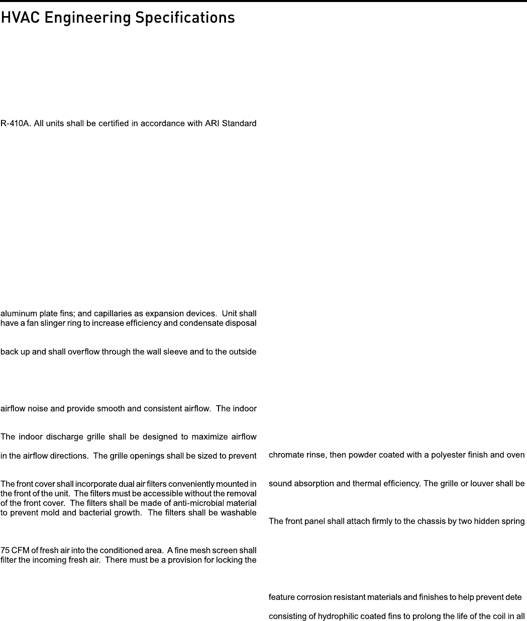
Digital Packaged Terminal Air Conditioners & Heat Pumps
All units shall be factory assembled, piped, wired and fully charged with
310 for air conditioners and ARI standard 380 for heat pumps. Units
shall be UL listed and carry a UL label. All units shall be factory run-
tested to check operation and be Friedrich or equivalent.
The basic unit shall not exceed 16” high x 42” wide. Overall depth
of the unit from the rear of the Friedrich wall sleeve to the front of
the decorative front cover shall not exceed 21 ¼”. The unit shall be
designed so that room int
rusion may be as little as 7 ½”. Installations
in walls deeper than 13 ¼” may be accomplished with the use of a
deep wall sleeve (PDXWSEXT). Unit shall draw in ambient air through
both sides of an outdoor architectural louver or grille measuring 42”
.revuol eht fo noitrop elddim tuo ria tsuahxe llahs dna hgih ”61 x ediw
The architectural louver and wall sleeve shall be designed so that the
louver may be installed f
rom the inside of the building.
REFRIGERATION SYSTEM – The refrigeration system shall be her-
metically sealed and consist of a rotary compressor that is externally
mounted on vibration isolators no smaller than 1 3/8” dia. x 1 ½” high;
condenser and evaporator coils constructed of copper tubes and
.etasnednoc fo snollag ½ 1 gniniater fo elbapac nap niard a evah dna
A tertiary condensate removal system shall also be incorporated for
of the building as a safeguard against damage to the interior room.
INDOOR AIR HANDLING SECTION – The indoor air handling sec-
tion shall consist of a tangential blower wheel direct driven by a totally
enclosed motor. The air handling system shall be designed to minimize
fan must have three fan speeds that may be selected by the user.
throughout the room. The grille shall be reversible to allow a change
personal injury or damage to the unit.
and reusable by cleaning with water or by vacuuming.
The chassis shall have a built-in damper capable of providing at least
damper closed to ensure a proper seal.
OUTDOOR AIR HANDLING SECTION – The outdoor air section
shall consist of a single injection molded fan shroud that incorporates
the outdoor motor mount into a single piece for ease of service and
assembly. The outdoor motor shall be totally enclosed, ball-bearing,
permanently lubricated and directly drive the outdoor fan/slinger ring.
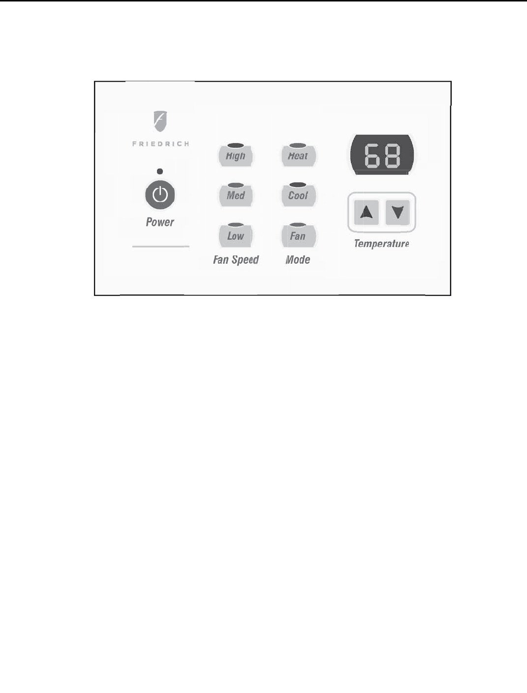
CONTROLS – Covered controls shall be accessible in a compartment
at least 7½” wide with the controls no deeper than 1 ¼” in the opening
to facilitate easy operation of the unit.
The unit controls shall feature a soft blue LED readout that can display
either room temperature or setpoint temperature. The unit shall re-
ceive input from the digital control panel through push buttons labeled:
‘Cool’, ‘Heat’, ‘High Fan’, ‘Med Fan’, ‘Low Fan’,
’, ‘’ and ‘Power’.
When ‘Off’, the unit may be put directly into cooling or heating mode
by pressing the ‘Cool’ or ‘Heat’ button.
The unit must have the following energy saving and convenience
features built-in:
• Quiet start/stop fan delay
• Fan cycle control for cooling and heating independently
• Room freeze protection
• Random compressor restart
• Electronic temperature limiting
The PTAC must also offer the ability to be controlled by a remote wall-
mounted thermostat wit
hout additional accessories. Low voltage inputs
will include: C (common), R (24V power), Y (cooling), GL (fan low), GH
(fan high), W (heat) and O (reversing valve on PDH heat pumps only).
PTAC models shall use a single stage cool / single stage heat ther-
mostat. PTHP models shall use a single stage cool / two-stage heat
thermostat. An accessory thermostat must be available from the
manufacturer, RT6 or equivalent. The RT6
thermostat will provide
.sedom naf dna taeh ,looc morf noitceles edom ,tnioptes erutarepmet
The thermostat must also allow the selection of fan speed between
high and low speed.
Other controls accessible without removal of the chassis shall include
fan cycle switch, fresh air vent control and emergency heat override
switch (heat pump only).
ELECTRICAL CONNECTION – All PTAC/PTHP units shall come from
the factory with a power cord installed. All 230/208V power cords shall
feature a leakage current detection device on the plug head. All units
shall feature a 6-pin connector for removal of the power cord. The
power cord shall be interchangeable to allow changes to the heater
output based on the property/electrical requirements.
GENERAL CONSTRUCTION – The wall sleeve shall be constructed
of 18-gauge Galvanized zinc-coated steel. It shall be prepared by
a process where it is zinc phosphate pretreated and sealed with a
cured for durability. The sleeve shall be shipped with a protective
weatherboard and a structural center support, and be insulated for
shipped separately and made from stamped or extruded anodized
aluminum. All louvers shall be in the horizontal plane.
clips. As an option the cover may be attached by two screws to pre-
vent tampering. The front panel will feature a contoured discharge
with no sharp corners.
CORROSION PROTECTION – The unit shall have corrosion-resistant
fans, fan shroud and drain pan for corrosion protection and to prevent
rust on the side of the building below the outdoor louver. The unit shall
-
rioration. The outdoor coil shall have Diamonblue corrosion protection
applications including seacoast environments. All outdoor coils shall
also have stainless steel endplates to eliminate rusting of the endplates.
WARRANTY – The warranty is one year on all parts and 5 years on
the sealed system including compressor, indoor and outdoor coils and
refrigerant tubing.
Cooling: 7600 – 15,000 Btuh
Heating: 7600 – 14500 Btuh (Heat Pump)
6824 – 17060 Btuh (Electric Heat)
Friedrich Models: PDE – Coo
ling with or without electric heat
PDH – Heat Pump with electric heat
7
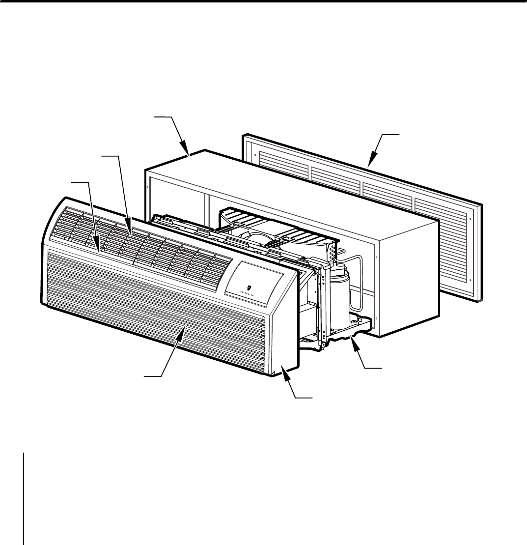
Component Identification
Typical Unit Components and Dimensions
FILTERS
RETURN AIR GRILLE
FRONT COVER
CHASSIS
OUTDOOR GRILLE
WALL SLEEVE
DISCHARGE
GRILLE
PDXWS Wall Sleeve Dimensions:
16" H x 42" W x 13-¾" D
Front Cover Dimensions:
16" H x 42" W x 7-¾" D
Cut-Out Dimensions:
16-¼" x 42-¼"
8
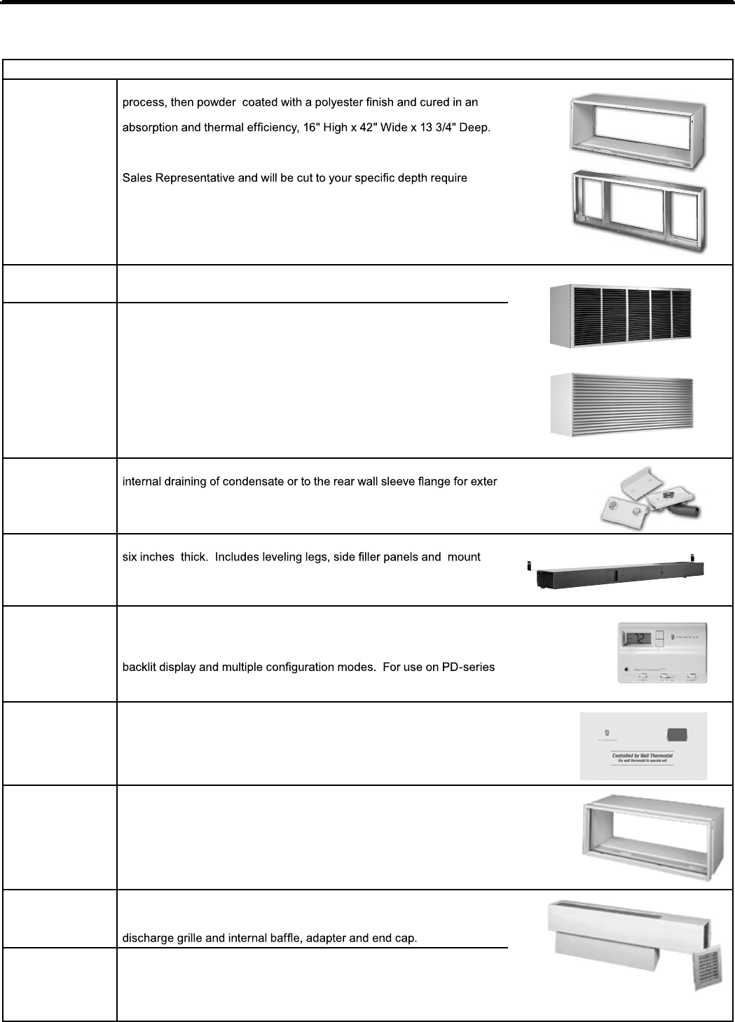
Accessories
PXAA
New Construction Accessories
PDXWS
PDXWSEXT
WALL SLEEVE Galvanized zinc coated steel is prepared in an 11-step
oven for exceptional durability. The wall sleeve is insulated for sound
DEEP WALL SLEEVE EXTENSION For use when the wall is thicker
than 13 1/4”deep. The wall sleeve may be special ordered through your
-
ments..
PXGA
GRILLE Standard, stamped aluminium, anodized to resist chalking and
oxidation.
PXAA
PXBG
PXSC
ARCHITECTURAL GRILLES Consist of heavy-gauge 6063-T5 alumi-
num alloy:
PXAA – Clear, extruded aluminum
PXBG – Beige acrylic enamel
PXSC – Also available in custom colors.
PXDR10
CONDENSATE DRAIN KIT Attaches to the bottom of the wall sleeve for
-
nal draining. Recommended on all units to remove excess condensate.
Packaged in quantities of ten.
PXSB
DECORATIVE SUBBASE Provides unit support for walls less than
-
ing brackets for electrical accessories. Accepts circuit breaker, power
disconnect switch, or conduit kit.
RT6
DIGITAL REMOTE WALL THERMOSTAT Single stage cool, single
stage heat for PDE models or single stage cool, dual stage heat for
PDH model thermostat features high/low fan speed switch. Thermostat
is hard wired and can be battery powered or unit powered. Features
Friedrich PTACs and Vert-I-Paks.
PDXRTA
REMOTE THERMOSTAT ESCUTCHEON KIT This kit contains ten
escutcheons that can be placed over the factory control buttons when
a remote wall mounted thermostat is used. The escutcheon directs the
guest to the wall thermostat for operation and retains the LED window to
display error codes and diagnostic information.
PXSE
SLEEVE EXTENSION RETROFIT KIT Galvanized zinc coated steel,
2.4" sleeve extension attached to the room side of the sleeve to allow for
the installation of a PD-Series Friedrich PTAC in a T-Series sleeve.
PDXDAA
LATERAL DUCT ADAPTER Attaches to the PTAC/PTHP unit and
provides a transition to direct up to 35% of the total CFM to a second-
ary room, either left or right of the unit. Kit includes duct plenum with
PDXDEA
LATERAL DUCT EXTENSION A three-foot insulated plenum that at-
taches to the left or right side of the duct adapter. The extension can be
cut to length by the installer. Maximum allowable straight extension is 15
feet.
PXGA
PDXWSEXT
PDXWS
Accessories
New Construction Accessories
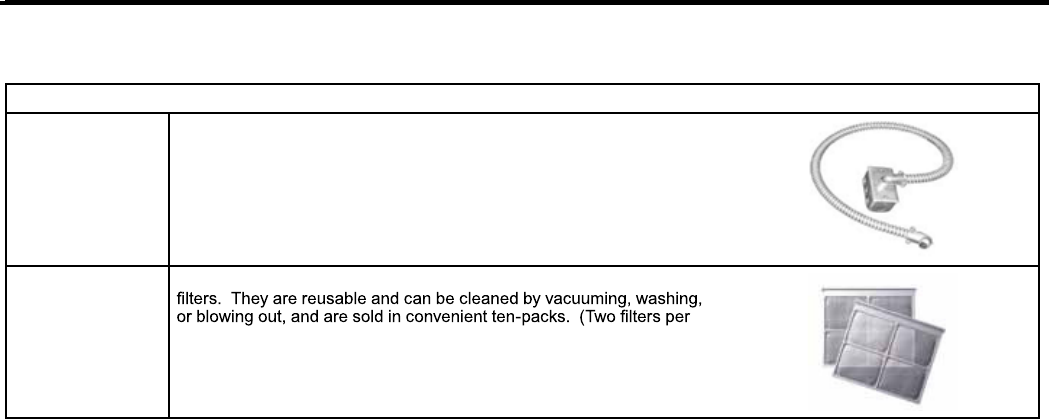
PXCJA
CONDUIT KIT WITH JUNCTION BOX Hard wire conduit kit with
junction box for 208/230V and 265V units (subbase not required). Kit
includes a means of quick disconnect for easy removal of the chassis.
*Required for 265V installations.
PXFTA
REPLACEMENT FILTER PACK These are original equipment return air
chassis).
9
A A A M 00001
LJ = 2009 AE = 2015
AK = 2010 AF = 2016
AA = 2011 AG = 2017
AB = 2012 AH = 2018
AC = 2013 AJ = 2019
AD = 2014
A = Jan D = Apr G = Jul K = Oct
B = Feb E = May H = Aug L = Nov
C = Mar F = Jun J = Sep M = Dec
PRODUCT LINE
M = PTAC
MONTH MANUFACTURED
PTAC Serial Number Identification Guide
SERIAL NUMBER
REBMUN NUR NOITCUDORPDERUTCAFUNAM RAEY
PD H 07 K 3 S F A
Engineering Digit
Design Series
Options
S = Standard
Nominal Heater Size
(@ 230V or 265V)
0 = No Heater
2 = 2KW
3 = 3KW
5 = 5.0KW
Voltage
K = 208/230V - 1Ph. - 60Hz.
R = 265V - 1Ph. - 60Hz.
Series
PD = P Series Digital PTAC
System
E = Cooling with or
without electric heat
H = Heat Pump with
Auxiliary Heat
Nominal Cooling Capacity
07 = 7000 BTUh
09 = 9000 BTUh
12 = 12000 BTUh
15 = 15000 BTUh
UNIT IDENTIFICATION
Model Number Code
10
250 V Receptacles and Fuse Types
AMPS 15 20 30
HEATER SIZE 0, 2.0 kW 3.0 kW 5.0 kW
RECEPTACLE
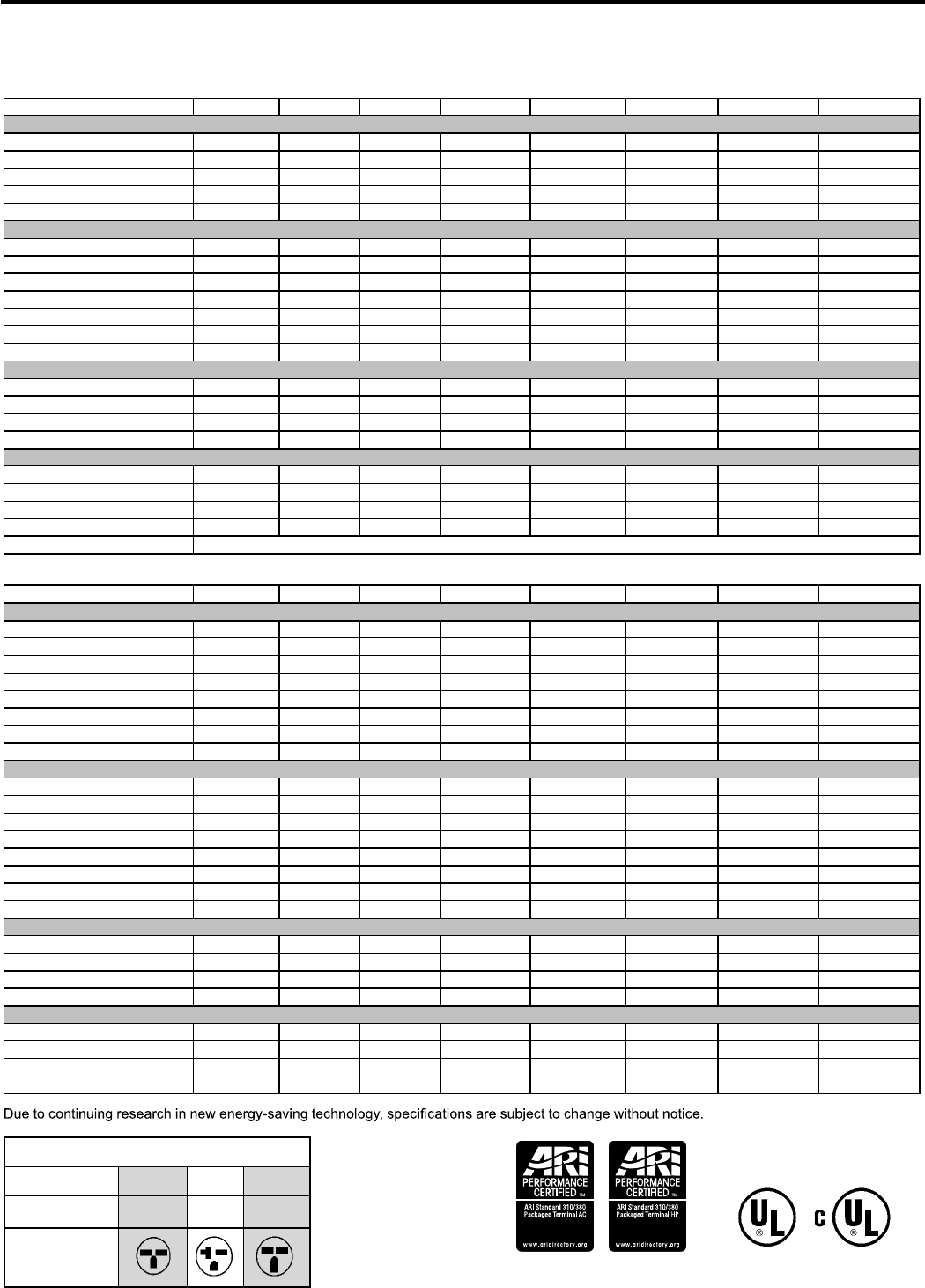
PDE Series
PDE07K PDE07R PDE09K PDE09R PDE12K PDE12R PDE15K PDE15R
PERFORMANCE DATA:
COOLING BTUh 7700/7600 7700 9000/8800 9000 12000/11800 12000 15000/14600 15000
POWER (WATTS) 640/620 640 800/770 800 1120/1120 1120 1530/1510 1530
EER 12.0/12.2 12.0 11.3/11.4 11.3 10.7/10.5 10.7 9.8/9.7 9.8
DEHUMIDIFICATION (pints/hr) 1.7 1.7 2.2 2.2 2.7 2.7 3.2 3.2
SENSIBLE HEAT RATIO 0.84 0.84 0.81 0.81 0.67 0.67 0.65 0.65
ELECTRICAL DATA:
VOLTAGE (1 PHASE, 60 Hz) 230/208 265 230/208 265 230/208 265 230/208 265
VOLT RANGE 253-187 292-239 253-187 292-239 253-187 292-239 253-187 292-239
CURRENT (AMPS) 2.8/3.0 2.4 3.7/3.9 3.7 5.1/5.3 4.8 6.7/7.5 5.9
POWER FACTOR 0.97 0.99 0.99 0.99 0.99 0.99 0.99 0.99
Compressor LRA 19.0 12.0 17.0 18.0 27.00 23.0 32.6 27.8
Compressor RLA 2.8 2.4 3.7 2.9 5.0 4.3 6.6 5.6
Fan motor horsepower 0.024 0.024 0.029 0.029 0.031 0.031 0.031 0.031
AIRFLOW DATA:
INDOOR CFM, HIGH 345/315 345 360/345 360 360/350 360 385/375 385
INDOOR CFM, MED 320/290 320 330/305 330 330/310 330 360/330 360
INDOOR CFM, LOW 295/265 295 300/270 300 310/280 310 320/290 320
VENT CFM 75 75 75 75 75 75 75 75
PHYSICAL DATA:
DIMENSIONS 16x42x13 3/4 16x42x13 3/4 16x42x13 3/4 16x42x13 3/4 16x42x13 3/4 16x42x13 3/4 16x42x13 3/4 16x42x13 3/4
NET WEIGHT 106 106 111 111 116 116 119 119
SHIPPING WEIGHT 126 126 131 131 136 136 139 139
R-410A CHARGE (oz) 23.63 24.69 33.51 33.51 35.27 35.98 38.1 40.21
Dim.s w/ Pkg. 19.75x23x 43.5 (all models)
PDH Series
PDH07K PDH07R PDH09K PDH09R PDH12K PDH12R PDH15K PDH15R
PERFORMANCE DATA:
COOLING BTUh 7700/7600 7700 9000/8800 9000 12000/11800 12000 14500/14200 14500
POWER (WATTS) cool 640/620 640 800/770 800 1120/1120 1120 1480/1460 1480
EER 12.0/12.2 12 11.3/11.4 11.3 10.7/10.5 10.7 9.8/9.7 9.8
REVERSE HEATING BTUh 6300/6100 6300 8100/7900 8100 10700/10500 10700 13300/13000 13300
POWER (WATTS) HEAT 540/530 540 720/770 720 1010/990 1010 1300/1270 1300
COP 3.4/3.4 3.4 3.3/3.3 3.3 3.1/3.1 3.1 3.0/3.0 3
DEHUMIDIFICATION (pints/hr) 1.7 1.7 2.2 2.2 2.7 2.7 3.2 3.2
SENSIBLE HEAT RATIO 0.84 0.84 0.81 0.81 0.67 0.67 0.65 0.65
ELECTRICAL DATA:
VOLTAGE (1 PHASE, 60 Hz) 230/208 265 230/208 265 230/208 265 230/208 265
VOLT RANGE 253-187 292-239 253-187 292-239 253-187 292-239 253-187 292-239
CURRENT (AMPS) 2.8/3.0 2.4 3.7/3.9 3.7 5.1/5.3 4.8 6.7/7.5 5.7
REVERSE HEAT. Amps 2.4/2.5 2.1 3.4/3.8 3.4 4.5/4.7 4.5 5.8/6.2 5.0
POWER FACTOR 0.97 0.99 0.99 0.99 0.99 0.99 0.98 0.98
Compressor LRA 19.0 12.0 18.5 19.0 27.00 23.0 36.0 26.0
Compressor RLA 2.8 2.4 3.6 3.2 5.0 4.3 6.5 5.3
Fan motor horsepower 0.024 0.024 0.029 0.029 0.031 0.031 0.031 0.031
AIRFLOW DATA:
INDOOR CFM, HIGH 345/315 345 360/345 360 360/350 360 420/390 385
INDOOR CFM, MED 320/290 320 330/305 330 330/310 330 410/380 360
INDOOR CFM, LOW 295/265 295 300/270 300 310/280 310 380/350 320
VENT CFM 75 75 75 75 75 75 75 75
PHYSICAL DATA:
DIMENSIONS 16x42x13.5 16x42x13.5 16x42x13.5 16x42x13.5 16x42x13.5 16x42x13.5 16x42x13.5 16x42x13.5
NET WEIGHT 108 108
113 113 118 118 121 123
SHIPPING WEIGHT 128 128 133 133 138 138 141 143
R-410A CHARGE (oz) 23.63 24.69 33.51 35.27 35.27 35.98 39.86 36.33
Chassis Specifications
11
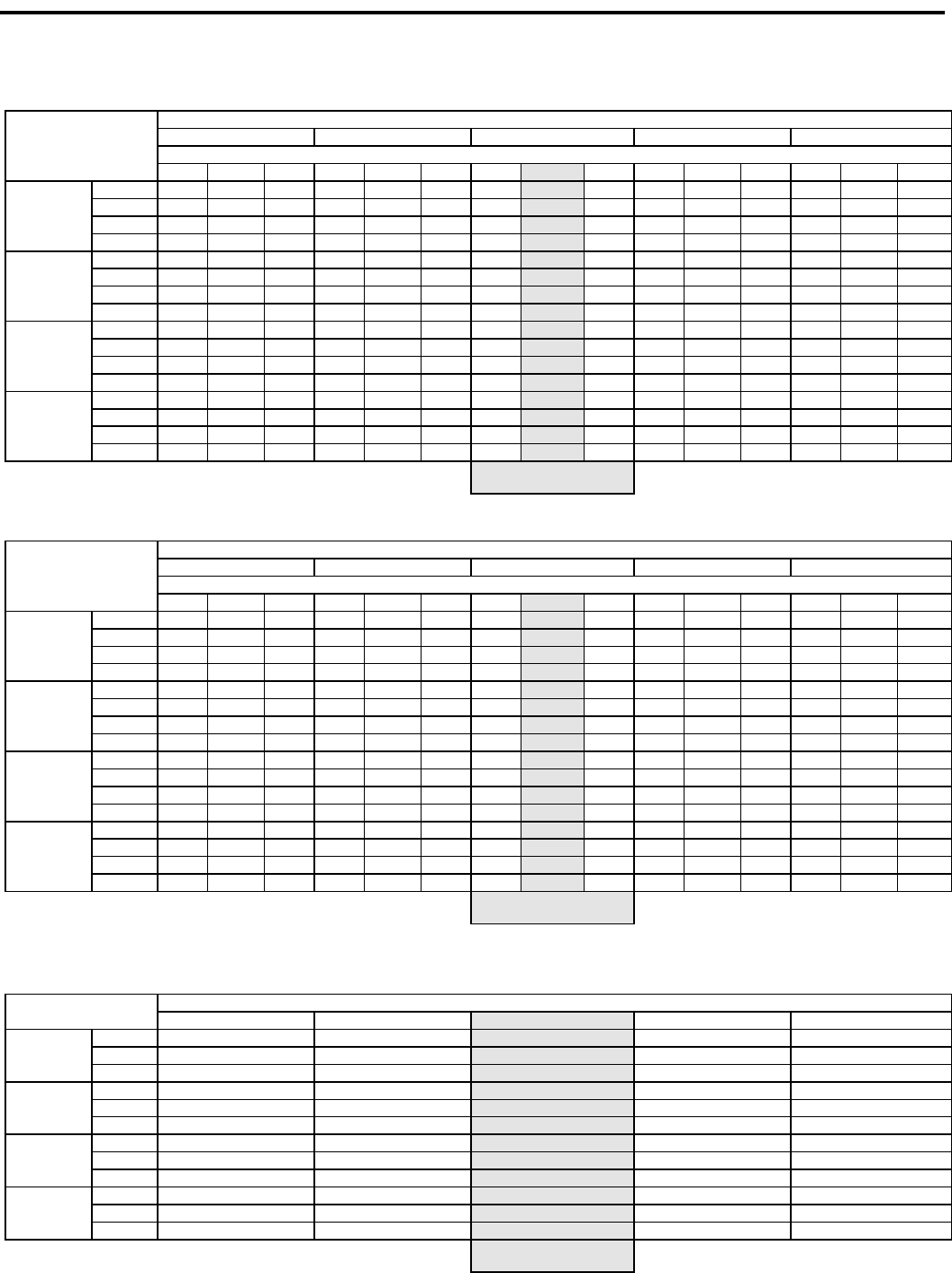
Cooling & Heating Performance
PDE 230V - Extended Cooling Performance
OUTDOOR DRY BULB TEMP. (DEGREES F AT 40% R.H.)
75 85 95 105 110
INDOOR WET BULB TEMP. (DEGREES F AT 80 F D.B.)
72 67 62 72 67 62 72 67 62 72 67 62 72 67 62
PDE07
BTUh 9055 8709 8062 8624 8131 7500 8285
7700
6815 7762 6892 6075 6907 5944 5251
WATTS 522 531 536 569 575 582 640
640
640 692 691 693 755 755 758
AMPS 2.3 2.3 2.4 2.5 2.5 2.5 2.8
2.80
2.8 3 3 3 3.3 3.3 3.3
SHR 0.53 0.72 0.96 0.54 0.74 0.98 0.54
0.77
0.99 0.55 0.81 0.99 0.58 0.87 0.99
PDE09
BTUh 10584 10179 9423 10080 9504 8766 9684
9000
7965 9072 8055 7101 8073 6948 6138
WATTS 653 663 670 711 718 727 800
800
800 865 864 866 943 943 947
AMPS 3.1 3.1 3.1 3.3 3.3 3.3 3.7
3.70
3.7 4 4 4 4.3 4.3 4.4
SHR 0.49 0.66 0.89 0.5 0.69 0.91 0.5
0.71
0.91 0.51 0.75 0.92 0.54 0.8 0.91
PDE12
BTUh 14112 13572 12564 13440 12672 11688 12912
12000
10620 12096 10740 9468 10764 9264 8184
WATTS 914 928 939 996 1006 1018 1120
1120
1120 1211 1210 1213 1320 1320 1326
AMPS 4.2 4.2 4.3 4.5 4.6 4.6 5.1
5.10
5.1 5.5 5.5 5.5 6 6 6
SHR 0.49 0.66 0.89 0.5 0.69 0.91 0.5
0.71
0.91 0.51 0.75 0.92 0.54 0.8 0.91
PDE15
BTUh 17640 16965 15705 16800 15840 14610 16140
15000
13275 15120 13425 11835 13455 11580 10230
WATTS 1248 1268 1282 1360 1374 1391 1530
1530
1530 1654 1652 1657 1804 1804 1812
AMPS 5.5 5.6 5.6 6 6 6 6.7
6.70
6.7 7.2 7.2 7.2 7.9 7.9 7.9
SHR 0.47 0.63 0.85 0.48 0.66 0.87 0.48
0.68
0.87 0.49 0.72 0.88 0.51 0.77 0.87
RATING POINT
ARI 310/380
PDH 230V - Extended Cooling Performance
OUTDOOR DRY BULB TEMP. (DEGREES F AT 40% R.H.)
75 85 95 105 110
INDOOR WET BULB TEMP. (DEGREES F AT 80 F D.B.)
72 67 62 72 67 62 72 67 62 72 67 62 72 67 62
PDH07
BTUh 9055 8709 8062 8624 8131 7500 8285
7700
6815 7762 6892 6075 6907 5944 5251
WATTS 522 531 536 569 575 582 640
640
640 692 691 693 755 755 758
AMPS 2.3 2.3 2.4 2.5 2.5 2.5 2.8
2.80
2.8 3 3 3 3.3 3.3 3.3
SHR 0.53 0.72 0.96 0.54 0.74 0.98 0.54
0.77
0.99 0.55 0.81 0.99 0.58 0.87 0.99
PDH09
BTUh 10584 10179 9423 10080 9504 8766 9684
9000
7965 9072 8055 7101 8073 6948 6138
WATTS 653 663 670 711 718 727 800
800
800 865 864 866 943 943 947
AMPS 3.1 3.1 3.1 3.3 3.3 3.3 3.7
3.70
3.7 4 4 4 4.3 4.3 4.4
SHR 0.49 0.66 0.89 0.5 0.69 0.91 0.5
0.71
0.91 0.51 0.75 0.92 0.54 0.8 0.91
PDH12
BTUh 14112 13572 12564 13440 12672 11688 12912
12000
10620 12096 10740 9468 10764 9264 8184
WATTS 914 928 939 996 1006 1018 1120
1120
1120 1211 1210 1213 1320 1320 1326
AMPS 4.2 4.2 4.3 4.5 4.6 4.6 5.1
5.10
5.1 5.5 5.5 5.5 6 6 6
SHR 0.49 0.66 0.89 0.5 0.69 0.91 0.5
0.71
0.91 0.51 0.75 0.92 0.54 0.8 0.91
PDH15
BTUh 17052 16400 15182 16240 15312 14123 15602
14500
12833 14616 12978 11441 13007 11194 9889
WATTS 1208 1227 1240 1316 1329 1345 1480
1480
1480 1600 1598 1603 1745 1745 1752
AMPS 5.4 5.5 5.5 5.9 5.9 5.9 6.5
6.6
6.6 7.1 7.1 7.1 7.7 7.7 7.7
SHR 0.48 0.65 0.88 0.49 0.68 0.89 0.49
0.70
0.9 0.5 0.74 0.9 0.53 0.79 0.9
RATING POINT
ARI 310/380
Extended Heating Performance
OUTDOOR DRY BULB TEMP. (DEGREES F)
37 42 47 52 57
PDH07
BTUh 5250 5540
6300
6900 7620
WATTS 509 518
540
549 580
AMPS 2.3 2.4
2.4
2.5 2.6
PDH09
BTUh 6005 6399
8100
8647 9245
WATTS 647 656
720
725 735
AMPS 3.3 3.3
3.4
3.4 3.5
PDH12
BTUh 7726 8531
10700
11278 12234
WATTS 883 917
1010
1039 1073
AMPS 4 4.1
4.5
4.7 4.9
PDH15
BTUh 10530 10850
13300
14550 15940
WATTS 1197 1212
1300
1377 1439
AMPS 5.3 5.4
5.8
6.1 6.3
RATING POINT
ARI 310/380
12
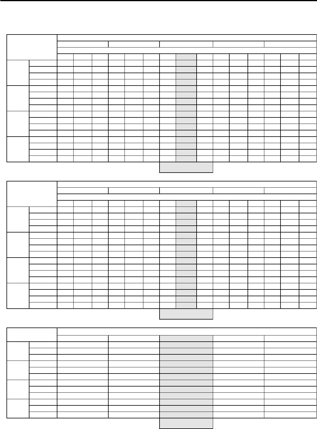
Cooling & Heating Performance
PDE 265V - Extended Cooling Performance
OUTDOOR DRY BULB TEMP. (DEGREES F AT 40% R.H.)
75 85 95 105 110
INDOOR WET BULB TEMP. (DEGREES F AT 80 F D.B.)
72 67 62 72 67 62 72 67 62
72 67 62 72 67 62
PDE07
BTUh 9055 8709 8062 8624 8131 7500 8285
7700
6815
7762 6892 6075 6907 5944 5251
WATTS 522 531 536 569 575 582 640
640
640
692 691 693 755 755 758
AMPS 2 2 2 2.1 2.1 2.2 2.4
2.40
2.4
2.6 2.6 2.6 2.8 2.8 2.8
SHR 0.53 0.72 0.96 0.54 0.74 0.98 0.54
0.77
0.99
0.55 0.81 0.99 0.58 0.87 0.99
PDE09
BTUh 10584 10179 9423 10080 9504 8766 9684
9000
7965
9072 8055 7101 8073 6948 6138
WATTS 653 663 670 711 718 727 800
800
800
865 864 866 943 943 947
AMPS 3.1 3.1 3.1 3.3 3.3 3.3 3.7
3.70
3.7
4 4 4 4.3 4.3 4.4
SHR 0.49 0.66 0.89 0.5 0.69 0.91 0.5
0.71
0.91
0.51 0.75 0.92 0.54 0.8 0.91
PDE12
BTUh 14112 13572 12564 13440 12672 11688 12912
12000
10620
12096 10740 9468 10764 9264 8184
WATTS 914 928 939 996 1006 1018 1120
1120
1120
1211 1210 1213 1320 1320 1326
AMPS 4 4 4 4.3 4.3 4.3 4.8
4.80
4.8
5.2 5.2 5.2 5.6 5.6 5.7
SHR 0.49 0.66 0.89 0.5 0.69 0.91 0.5
0.71
0.91
0.51 0.75 0.92 0.54 0.8 0.91
PDE15
BTUh 17640 16965 15705 16800 15840 14610 16140
15000
13275
15120 13425 11835 13455 11580 10230
WATTS 1248 1268 1282 1360 1374 1391 1530
1530
1530
1654 1652 1657 1804 1804 1812
AMPS 4.9 4.9 5 5.3 5.3 5.3 5.9
5.90
5.9
6.3 6.3 6.4 6.9 6.9 7
SHR 0.47 0.63 0.85 0.48 0.66 0.87 0.48
0.68
0.87
0.49 0.72 0.88 0.51 0.77 0.87
RATING POINT
ARI 310/380
PDH 265V - Extended Cooling Performance
OUTDOOR DRY BULB TEMP. (DEGREES F AT 40% R.H.)
75 85 95
105 110
INDOOR WET BULB TEMP. (DEGREES F AT 80 F D.B.)
72 67 62
72 67 62 72 67 62 72 67 62 72 67 62
PDH07
BTUh 9055 8709 8062 8624 8131 7500 8285
7700
6815 7762 6892 6075 6907 5944 5251
WATTS 522 531 536 569 575 582 640
640
640 692 691 693 755 755 758
AMPS 2 2 2 2.1 2.1 2.2 2.4
2.40
2.4 2.6 2.6 2.6 2.8 2.8 2.8
SHR 0.53 0.72 0.96 0.54 0.74 0.98 0.54
0.77
0.99 0.55 0.81 0.99 0.58 0.87 0.99
PDH09
BTUh 10584 10179 9423 10080 9504 8766 9684
9000
7965 9072 8055 7101 8073 6948 6138
WATTS 653 663 670 711 718 727 800
800
800 865 864 866 943 943 947
AMPS 3.1 3.1 3.1 3.3 3.3 3.3 3.7
3.70
3.7 4 4 4 4.3 4.3 4.4
SHR 0.49 0.66 0.89 0.5 0.69 0.91 0.5
0.71
0.91 0.51 0.75 0.92 0.54 0.8 0.91
PDH12
BTUh 14112 13572 12564 13440 12672 11688 12912
12000
10620 12096 10740 9468 10764 9264 8184
WATTS 914 928 939 996 1006 1018 1120
1120
1120 1211 1210 1213 1320 1320 1326
AMPS 4 4 4 4.3 4.3 4.3 4.8
4.80
4.8 5.2 5.2 5.2 5.6 5.6 5.7
SHR 0.49 0.66 0.89 0.5 0.69 0.91 0.5
0.71
0.91 0.51 0.75 0.92 0.54 0.8 0.91
PDH15
BTUh 17052 16400 15182 16240 15312 14123 15602
14500
12833 14616 12978 11441 13007 11194 9889
WATTS 1208 1227 1240 1316 1329 1345 1480
1480
1480 1600 1598 1603 1745 1745 1752
AMPS 4.7 4.7 4.8 5.1 5.1 5.1 5.7
5.7
5.7 6.1 6.1 6.2 6.7 6.7 6.7
SHR 0.48 0.65 0.88 0.49 0.68 0.89 0.49
0.70
0.9 0.5 0.74 0.9 0.53 0.79 0.9
RATING POINT
ARI 310/380
Extended Heating Performance
OUTDOOR DRY BULB TEMP. (DEGREES F)
37 42 47 52 57
PDH07
BTUh 5250 5540
6300
6900 7620
WATTS 509 518
540
549 580
AMPS 2.3 2.4
2.4
2.5 2.6
PDH09
BTUh 6005 6399
8100
8647 9245
WATTS 647 656
720
725 735
AMPS 3.3 3.3
3.4
3.4 3.5
PDH12
BTUh 7726 8531
10700
11278 12234
WATTS 883 917
1010
1039 1073
AMPS 4 4.1
4.5
4.7 4.9
PDH15
BTUh 10530 10850
13300
14550 15940
WATTS 1197 1212
1300
1377 1439
AMPS 4.5 4.6
5
5.3 5.5
RATING POINT
ARI 310/380
13

Electric Heat Data
Electric Heat Data
PDE07K0 PDE/PDH07K PDE/PDH07R
HEATER WATTS 0 Kw 2000 1635 3000 2450 2000 3000
VOLTAGE 230/208 230 208 230 208 265
HEATING BTUh 0 6824 5580 10236 8360 6824 10236
HEATING CURRENT (AMPS) 0 8.9 7.9 13.2 12.2 7.6 11.4
MINIMUM CIRCUIT AMPACITY 4.0 11.4 10.0 16.8 15.6 9.6 14.6
BRANCH CIRCUIT FUSE (AMPS) 15 15 15 20 20 15 20
Electric Heat Data
PDE09K0 PDE/PDH09K PDE/PDH09R
HEATER WATTS 0 Kw 2000 1635 3000 2450 5000 4090 2000 3000 5000
VOLTAGE 230/208 230 208 230 208 230 208 265
HEATING BTUh 0 6824 5580 10236 8360 17060 13960 6824 10236 17060
HEATING CURRENT (AMPS) 0 8.9 7.9 13.2 12.2 21.5 20.5 7.6 11.4 19.0
MINIMUM CIRCUIT AMPACITY 5.2 11.4 10.0 16.8 15.6 27.2 26.0 9.8 14.6 24.1
BRANCH CIRCUIT FUSE (AMPS) 15 15 15 20 20 30 30 15 20 30
Electric Heat Data
PDE12K0 PDE/PDH12K PDE/PDH12R
HEATER WATTS 0 Kw 2000 1635 3000 2450 5000 4090 2000 3000 5000
VOLTAGE 230/208 230 208 230 208 230 208 265
HEATING BTUh 0 6824 5580 10236 8360 17060 13960 6824 10236 17060
HEATING CURRENT (AMPS) 0 8.9 7.9 13.2 12.2 21.5 20.5 7.6 11.4 19.0
MINIMUM CIRCUIT AMPACITY 7.1 11.4 10.0 16.8 15.6 27.2 26.0 9.8 14.6 24.1
BRANCH CIRCUIT FUSE (AMPS) 15 15 15 20 20 30 30 15 20 30
Electric Heat Data
PDE15K0 PDE/PDH15K PDE/PDH15R
HEATER WATTS 0 Kw 2000 1635 3000 2450 5000 4090 2000 3000 5000
VOLTAGE 230/208 230 208 230 208 230 208 265
HEATING BTUh 0 6824 5580 10236 8360 17060 13960 6824 10236 17060
HEATING CURRENT (AMPS) 0 8.9 7.9 13.2 12.2 21.5 20.5 7.6 11.4 19.0
MINIMUM CIRCUIT AMPACITY 9.1 11.4 10.0 16.8 15.6 27.2 26.0 9.8 14.6 24.1
BRANCH CIRCUIT FUSE (AMPS) 15 15 15 20 20 30 30 15 20 30
14
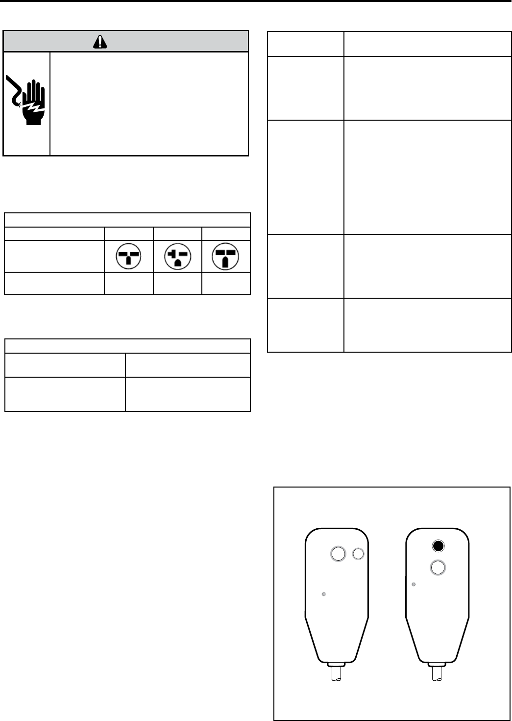
Table 1 250 V Receptacles and Fuse Types
AMPS 15 20* 30
RECEPTACLE
TIME-DELAY TYPE FUSE
(or HACR circuit breaker)
15 20 30
ELECTRICAL RATING TABLES
HACR – Heating, Air Conditioning, Refrigeration
* May be used for 15 Amp applications if fused for 15 Amp
NOTE: 265 volt units are hard wired.
AWG – American Wire Gauge
* Single circuit from main box
** Based on copper wire, single insulated conductor at 60°C
WIRE SIZE
Use ONLY wiring size recommended for
single outlet branch circuit.
FUSE/CIRCUIT
BREAKER
Use ONLY type and size fuse or HACR
circuit breaker indicated on unit’s rating
plate. Proper current protection to the unit
is the responsibility of the owner. NOTE:
A time delay fuse is provided with 265V
units.
GROUNDING
Unit MUST be grounded from branch
circuit through service cord to unit, or
through separate ground wire provided
on permanently connected units. Be sure
that branch circuit or general purpose
outlet is grounded. The fi eld supplied
outlet must match plug on service cord
and be within reach of service cord. Refer
to Table 1 for proper receptacle and fuse
type. Do NOT alter the service cord or
plug. Do NOT use an extension cord.
RECEPTACLE
The fi eld supplied outlet must match plug
on service cord and be within reach of
service cord. Refer to Table 1 for proper
receptacle and fuse type. Do NOT alter
the service cord or plug. Do NOT use an
extension cord.
WIRE SIZING
Use recommended wire size given
in Table 2 and install a single branch
circuit. All wiring must comply with local
and national codes. NOTE: Use copper
conductors only.
Table 2 Recommended branch circuit wire sizes*
NAMEPLATE / MAXIMUM
CIRCUIT BREAKER SIZE
AWG WIRE SIZE**
15
20
30
14
12
10
NOTE: Use Copper Conductors ONLY. Wire sizes
are per NEC, check local codes for overseas applica-
tions.
ELECTRIC SHOCK HAZARD
WARNING
Turn off electric power before service or
installation. All electrical connections and
wiring MUST be installed by a qualifi ed
electrician and conform to the National
Electrical Code and all local codes which
have jurisdiction. Failure to do so could result
in serious personal injury or death.
15
POWER CORD INFORMATION (230/208V MODELS ONLY)
All Friedrich 230/208V PTAC units are shipped from the
factory with a Leakage Current Detection Interrupter (LCDI)
equipped power cord. The LCDI device meets the UL and
NEC requirements for cord connected air conditioners
effective August 2004.
To test your power supply cord:
1. Plug power supply cord into a grounded 3 prong outlet.
2. Press RESET.
3. Press TEST (listen for click; Reset button trips and pops
out).
4. Press and release RESET (listen for click; Reset button
latches and remains in). The power supply cord is ready for
operation.
NOTE: The LCDI device is not intended to be used as a
switch.
Once plugged in the unit will operate normally without the
need to reset the LCDI device. If the LCDI device trips and
W ARNING
15/20A LCDI Device 30A LCDI Device
TEST BEFORE EACH USE
1. PRESS RESET BUTT ON
2. PLUG LCDI INT O POWER
RECEPT ACLE
3. PRESS TEST BUTT ON,
RESET BUTT ON SHOULD
POP UP
4. PRESS TEST BUTT ON,
FOR USE
DO NOT USE IF ABOVE TEST
F AILS
WHEN GREEN LIGHT IS ON
IT IS WORKING PROPERL Y
RESET
TEST
W ARNING
TEST BEFORE EACH USE
1. PRESS RESET BUTT ON
2. PLUG LCDI INT O POWER
RECEPT ACLE
3. PRESS TEST BUTT ON,
RESET BUTT ON SHOULD
POP UP
4. PRESS TEST BUTT ON,
FOR USE
DO NOT USE IF ABOVE TEST
F AILS
WHEN GREEN LIGHT IS ON
IT IS WORKING PROPERL Y
RESET
TEST
FRP014
Typical LCDI Devices
16
Model Heater kW Power Cord Kit Voltage Amperage Receptacle
PDE07K 0.0 PXPC23000 230/208 15 NEMA.6-15r
PDE/PDH07K 2.0 PXPC23015 230/208 15 NEMA.6-15r
3.0 STD 230/208 20 NEMA.6-20r
PDE09K 0.0 PXPC23000 230/208 15 NEMA.6-15r
PDE/PDH09K 2.0 PXPC23015 230/208 15 NEMA.6-15r
3.0 STD 230/208 20 NEMA.6-20r
5.0 PXPC23030 230/208 30 NEMA.6-30r
PDE12K 0.0 PXPC23000 230/208 15 NEMA.6-15r
PDE/PDH12K 2.0 PXPC23015 230/208 15 NEMA.6-15r
3.0 STD 230/208 20 NEMA.6-20r
5.0 PXPC23030 230/208 30 NEMA.6-30r
PDE15K 0.0 PXPC23000 230/208 15 NEMA.6-15r
PDE/PDH15K 2.0 PXPC23015 230/208 15 NEMA.6-15r
3.0 PXPC23020 230/208 20 NEMA.6-20r
5.0 STD 230/208 30 NEMA.6-30r
PDE/PDH07R 2.0 PXPC26515 265 15 NEMA.6-15r
3.0 STD 265 20 NEMA.6-20r
PDE/PDH09R 2.0 PXPC26515 265 15 NEMA.6-15r
3.0 STD 265 20 NEMA.6-20r
5.0 PXPC26530 265 30 NEMA.6-30r
PDE/PDH12R 2.0 PXPC26515 265 15 NEMA.6-15r
3.0 STD 265 20 NEMA.6-20r
5.0 PXPC26530 265 30 NEMA.6-30r
PDE/PDH15R 2.0 PXPC26515 265 15 NEMA.6-15r
3.0 PXPC26520 265 20 NEMA.6-20r
5.0 STD 265 30 NEMA.6-30r
Electrical Wiring for 265 Volt
Models
NOTE: It is recommended that the PXSB subbase assembly, the
PXCJA conduit kit (or equivalent) be installed on all hardwire
units. If installing a
mounted unit, make sure the
chassis can be removed from the sleeve for service and
maintenance.
WARNING
Electrical Shock Hazard
Turn off electrical power before service
or installation.
ALL electrical connections and wiring
MUST be installed by a qualified
electrician and conform to the National
Code and all local codes which have
jurisdiction.
Failure to do so can result in property
damage, personal injury and/or death.
Power Cord Installation
All 265V PTAC/PTHP units come with a factory installed non-LCDI
power cord for use in a subbase. If the unit is to be hard-wired refer to
the instructions below.
To install the line voltage power leads and conduit
to chassis, follow the instructions below.
PXCJA Conduit Kit
is required with this setup.
1. Follow
listed in the installation manual (Figure 25, step 2, page 19).
the removal process of the chassis’s junction box..
2. .Prepare the 265V (or 230V) power cord for connection to the chas-
sis’ power cord connector by cutting the cord to the appropriate
length (Figure15). Power cord harness selection shown on Table
above.
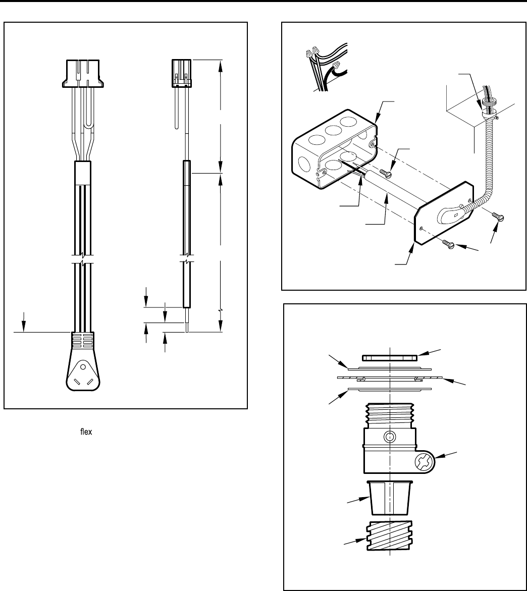
3. Route the cut ends of harness through the conduit connector
assembly and
conduit sleeve. Be sure to use the supplied
conduit bushing to prevent damage to the cord by the conduit.
The cord should pass through the Locknut, Spacer, Chassis
Junction Box, Conduit Connector, Bushing, then the Conduit
Sleeve. Refer to wire harness insertion diagram.
4. Route the cut ends of the power cord through the elbow connector
at the other end of the conduit. Tighten screws on elbow connector
to secure conduit sleeve.
5. Fasten and secure the elbow connector to the wall junction box
cover with locknut. Place and mount the wall junction box with
the four wall mounting screws making sure to pass the wall lines
through the junction box. Connect and join all wall lines with the
stripped ends using wire nuts. Tighten both screws of the wall
junction box cover to junction box.
FRP032
4.0 IN.
18.0 IN.
TRIM HARNESS
TO LENGTH
STRIP WIRE ENDS (0.5 IN.)
TO WALL JUNCTION
TO CHASSIS JUNCTION
EXPOSE
WIRES
(1.0 IN.)
FRP033
GROUND
SCREW
GROUND
WIRE
HARNESS
JUNCTION
BOX
WALL CONNECTION
JUNCTION
BOX COVER
COVER
SCREWS
STRAIGHT
CONNECTOR
FRP034
LOCKNUT
SPACER
SPACER
BUSHING
LEADING SIDE FOR
WIRE HARNESS INSERTION
EXITING SIDE FOR
WIRE HARNESS
CHASSIS
JUNCTION
BOX
CONDUIT
CONNECTOR
CONDUIT
SLEEVE
17
Remote Control Thermostat
Installation
Install Thermostat
1. Approximately 5 ft. from the
2. Close to or in a frequently used room, preferably on an inside wall.
3. On a section of wall without pipes or ductwork.
The Thermostat should NOT be mounted:
1. Close to a window, on an outside wall, or next to a door leading
outside.
2. Where it can be exposed to direct sunlight or heat, such as the sun,
a lamp,
or any temperature radiating object which
may cause a false reading.
3. Close to or in the direct
of supply registers and/or return
air grilles.
4. Any areas with poor air circulation, such as a corner, behind a
door, or an alcove.
Remote Thermostat and Low
Voltage Control Connections
Remote Thermostat
All Friedrich PD model PTAC units are factory
to be controlled
by either the chassis mounted Smart Center or a 24V remote wall mounted
thermostat. The thermostat may be auto or manual changeover as long as
the control
matches that of the PTAC unit.
NOTE: All PDE models require a single stage cool, single stage heat.
thermostat. All PDH models require a single stage cool, dual.
stage heat thermostat with an O reversing valve control. The
Friedrich RT6 thermostat can be
for either model.
FRP029
F
RP029
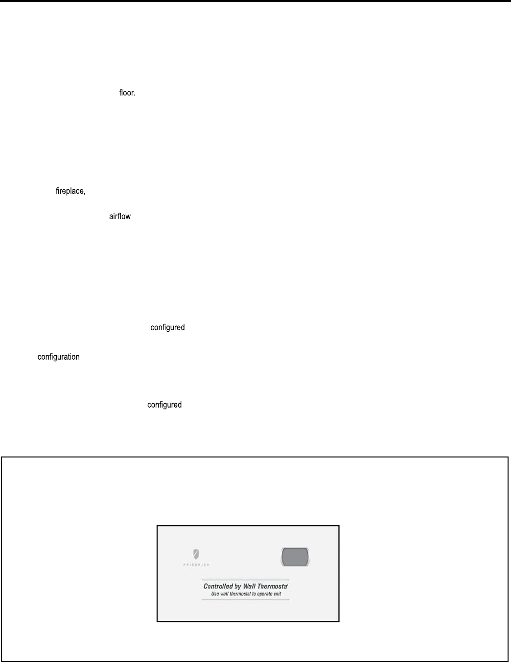
Control board with optional PDXRT escutcheon kit installed
To control the unit with a wall mounted thermostat
follow the steps below:
1. Unplug the unit before doing any work.
2. With the front.cover removed locate the dip switches located below
the Smart Center control panel. Switch Dip switch 2 to the up on
'ON' position.
3. Remove the low voltage terminal block from the unit.
4. Connect the corresponding terminals from the wall thermostat to
the terminal block.
5. Replace the terminal block on the unit.
6. Restore power to the unit.
7. The unit is now controlled by the wall thermostat only.
8. If the accessory escutcheon kit (PDXRTA) is to be used, install it
over the existing control panel.
NOTE:. The unit mounted controls no longer control the unit. To restore
the unit mounted controls move dip switch 2 to the down or
'OFF' position.
Thermostat Connections
R = 24V Power from Unit
Y = Call for Cooling
W =
=
Call for Heating
O Reversing Valve Energized in cooling mode (PDH Models Only)
GL = Call for Low Fan
GH = Call for High Fan
C = Common Ground
*If only one G terminal is present on thermostat connect to GL for low
speed fan or to GH for high speed fan operation.
18
26
Desk Control Terminals
The Friedrich PD model PTAC has built-in provisions for connection to an
external switch to control power to the unit. The switch can be a central
desk control system or even a normally open door switch.
For desk control operation connect one side of the switch to the D1 terminal
and the other to the D2 terminal. Whenever the switch closes the unit
operation will stop.
NOTE: The desk control system and switches must be
supplied.
Energy Management
Sometimes known as Front Desk Control, an input is provided so that the
unit can be manually disabled from a remote location. If the unit detects
24Vac on this input, it will automatically turn itself off. If no voltage is
detected on the input , the unit will run normally.
NOTE: It is the installer's responsibility to ensure that all control.wiring
connections are made in accordance with the installation
instructions. Improper connection of the thermostat control
wiring and/or tampering with the unit's internal wiring can
void the equipment warranty. Other manufacturer's PTACs
and even older Friedrich models may have different control
wire connections. Questions concerning proper connections
to the unit should be directed to Friedrich.
WARNING
Electrical Shock Hazard
Turn off electrical power before service
or installation.
ALL electrical connections and wiring
MUST be installed by a qualified
electrician and conform to the National
Code and all local codes which have
jurisdiction.
Improper connection of the thermostat
control wiring and/or tampering with the
units internal wiring may result in property
damage, personal injury or death.
19

FRIEDRICH DIGITAL CONTROL FEATURES
The new Friedrich digital PTAC has state of the art features to improve guest comfort, indoor air quality and conserve
energy. Through the use of specifi cally designed control software for the PTAC industry Friedrich has accomplished
what other Manufacturer’s have only attempted – a quiet, dependable, affordable and easy to use PTAC.
Below is a list of standard features on every Friedrich PTAC and their benefi t to the owner.
Digital Temperature
Readout
By digitally monitoring desired room temperature the room is controlled more precisely than conventional
systems. The large, easy to read LED display can show either set-point or actual room temperature as
selected by owner.
One-Touch
Operation
When the unit is powered off the unit can be returned directly to heating or cooling mode by pressing the
‘Heat’ or ‘Cool’ buttons without the confusing power up sequence of some controls. One-touch control
takes guess-work out of unit control delivering a more enjoyable experience and eliminating front-desk
calls.
Individual Mode and
Fan Control Buttons
By having separate control buttons and indicators for both fan and mode settings the Friedrich digital con-
trol eliminates the confusion of previous digital PTACs. The accurate temperature setting provides greater
guest comfort than other systems.
Quiet Start/Stop
Fan Delay
The fan start and stop delays prevent abrupt changes in room acoustics due to the compressor energizing
or stopping immediately. Upon call for cooling or heating the unit fan will run for fi ve seconds prior to en-
ergizing the compressor. Also, the fan off delay allows for “free cooling” by utilizing the already cool indoor
coil to its maximum capacity by running for 30 seconds after the compressor.
Remote Thermostat
Operation
Some applications require the use of a wall mounted thermostat. All new Friedrich PTACs may be switched
from unit control to remote thermostat control easily without the need to order a special model or acces-
sory kit.
Wireless Remote
Control Ready
Guests can adjust the temperature and mode of the unit through the use of an optional hand held wireless
remote, improving guest comfort and relaxation.
Internal Diagnostic
Program
The new Friedrich digital PTAC features a self diagnostic program that can alert maintenance to compo-
nent failures or operating problems. The internal diagnostic program saves properties valuable time when
diagnosing running problems.
Service Error Code
Storage
The self diagnosis program will also store error codes in memory if certain conditions occur and correct
themselves such as extreme high or low operating conditions or activation of the room freeze protection
feature. Storing error codes can help properties determine if the unit faced obscure conditions or if an error
occurred and corrected itself.
Constant Comfort
Room Monitoring
The on-board processor monitors time between demand cycles (heat or cool) and will cycle the fan every
9 minutes to sample the room condition and determine if the desired conditions are met. This allows the
room to have similar benefi ts to a remote mounted stat without the complication or cost of a wall mounted
thermostat.
Electronic
Temperature
Limiting
By limiting the operating range the property can save energy by eliminating “max cool” or “max heat” situ-
ations common with older uncontrolled systems. The new electronic control allows owners to set operating
ranges for both heating and cooling independently of one another.
Room Freeze
Protection
When the PTAC senses that the indoor room temperature has fallen to 40°F the unit will cycle on high fan
and the electric strip heat to raise the room temperature to 46°F then cycle off again. This feature works
regardless of the mode selected and can be turned off. The control will also store the Room Freeze cycle
in the service code memory for retrieval at a later date. This feature ensures that unoccupied rooms do not
reach freezing levels where damage can occur to plumbing and fi xtures.
Random
Compressor Restart
Multiple compressors starting at once can often cause electrical overloads and premature unit failure.
The random restart delay eliminates multiple units from starting at once following a power outage or initial
power up. The compressor delay will range from 180 to 240 seconds.
20
!
FRP030
F
RP
030
!"#$%" &"'($)*+,
!"# $%&'# &(# )*+',-.# +,%/0$-"1# ',# 1&(23*.# *33# '"42"-*'$-"(# &%# 1"0-""(#
5*!-"%!"&'#67#589# ,#(:&'+!#',#1"0-""(#;"3(&$(#2-"((#'!"#<5*%#=%3.>#*%1#
<?,:#5*%>#@$'',%(#(&4$3'*%",$(3.#),-#'!-""#("+,%1(9# !"#1&(23*.#:&33#(!,:#
*#<;>#*(#*+A%,:3"10"4"%'#,)#'!"#+!*%0"9## ,#-"B"-'#@*+A#',#7#5#2-"((#'!"#
<5*%#=%3.>#*%1#<?,:#5*%>#@$'',%(#(&4$3'*%",$(3.#),-#'!-""#("+,%1(9# !"#
1&(23*.#:&33#(!,:#*%#<5>#*(#*+A%,:3"10"4"%'#,)#'!"#+!*%0"9
&--*(./"0-12
C-"((&%0#'!"#<;,,3>#@$'',%#:!&3"#'!"#$%&'#&(#&%# *%.#4,1"D#&%+3$1&%0#,))D#
:&33#2$'#'!"#$%&'#&%',#+,,3&%0#4,1"9#E1F$('#'!"#'"42"-*'$-"#-"*1,$'#',#'!"#
1"(&-"1#-,,4#'"42"-*'$-"#*%1#'!"#$%&'#:&33#+.+3"#'!"#+,42-"((,-#,%#*%1#
,))#',#4*&%'*&%#*#+,4),-'*@3"#-,,49# !"#+,42-"((,-#:&33#+,4"#,%#*%.'&4"#
'!*'#'!"#-,,4#'"42"-*'$-"#&(#G9H7#5#*@,B"#'!"#1"(&-"1#'"42"-*'$-"9# !"#
)*%#,2"-*'&,%#&(#1"2"%1"%'#,%#'!"#)*%#4,1"#("3"+'"1D#"&'!"-#+,%'&%$,$(#
,-#+.+3&%09##I""#5*%#J,1"#),-#)*%#+.+3"#+,%'-,39
32+4(./"0-12
C-"((&%0#'!"#<K"*'>#@$'',%#:!&3"#'!"#$%&'#&(#&%#*%.#4,1"D#&%+3$1&%0#,))D#:&33#
2$'#'!"#$%&'#&%',#!"*'&%0#4,1"9
32+4"567)"0-12*$"85'39
L!"%#'!"#<K"*'>#@$'',%#&(#2-"(("1#&%&'&*33.#'!"#$%&'#:&33#"%"-0&M"#'!"#"3"+'-&+#
-"(&('*%+"#!"*'#',#N$&+A3.#@-&%0#'!"#-,,4#',#'!"#("'#'"42"-*'$-"9##L!"%#'!"#
1"(&-"1#-,,4#'"42"-*'$-"#)*33(#G9H7#5#@"3,:#'!"#1"(&-"1#("'#'"42"-*'$-"#'!"#
$%&'#:&33#+.+3"#'!"#+,42-"((,-#,%#*%1#,2"-*'"#*(#*#!"*'#2$42#',#4*&%'*&%#
'!"#-,,4#'"42"-*'$-"#:!&3"#-$%%&%0#4,-"#")/+&"%'3.#'!*%#-"(&('*%+"#!"*'#
,%3.#4,1"3(9##O)#'!"#-,,4#'"42"-*'$-"#(!,$31#)*33#4,-"#'!*%#P7#5#)-,4#'!"#
("'#'"42"-*'$-"#'!"#$%&'#:&33#-$%#'!"#-"(&('*%+"#!"*'"-9## !"#)*%#,2"-*'&,%#
&(#1"2"%1"%'#,%#'!"#)*%#4,1"#("3"+'"1D#"&'!"-#+,%'&%$,$(#,-#+.+3&%09#Q&2#
(:&'+!#R#+,%'-,3(#'!"#)*%#4,1"D#(""#2*0"#SR#),-#("''&%09##
L!"%#'!"#,$'1,,-#+,&3#'"42"-*'$-"#)*33(#@"3,:#RT7#5#),-#4,-"#'!*%#S#4&%U
$'"(#'!"#$%&'#:&33#,2"-*'"#'!"#-"(&('*%+"#!"*'"-(#*%1#%,'#'!"#+,42-"((,-9##
L!"%#'!"#,$'1,,-#+,&3#'"42"-*'$-"#-"*+!"(#VP7#5#'!"#+,42-"((,-#:&33#@"#
*33,:"1#',#,2"-*'"#*0*&%9
32+4:&--*"0-12*$"85';9
E)'"-#2-"((&%0#'!"#<K"*'># @$'',%D#*1F$('#'!"#'"42"-*'$-"#-"*1,$'# ',#'!"#
1"(&-"1#-,,4#'"42"-*'$-"#*%1#'!"#$%&'#:&33#+.+3"#'!"#-"(&('*%+"#!"*'#,%#
*%1#,))#',#4*&%'*&%#*#+,4),-'*@3"#-,,49# !"#!"*'"-#:&33#+,4"#,%#*%.'&4"#
'!*'#'!"#-,,4#'"42"-*'$-"#&(#G9H7#5#@"3,:#'!"#1"(&-"1#'"42"-*'$-"9# !"#
)*%#,2"-*'&,%#&(#1"2"%1"%'#,%#'!"#)*%#4,1"#("3"+'"1D#"&'!"-#+,%'&%$,$(#
,-#+.+3&%09#Q&2#(:&'+!#R#+,%'-,3(#'!"#)*%#4,1"D#(""#2*0"#SR#),-#("''&%09
;72</2.=,"32+4">)2<+4(-.
O%#'!"#"B"%'#,)#*#+,42-"((,-#)*&3$-"#&%#!"*'#2$42#4,1"#'!"#+,42-"((,-#4*.#
@"#3,+A"1#,$'#',#2-,B&1"#!"*'#'!-,$0!#'!"#-"(&('*%+"#!"*'"-9# !&(#)"*'$-"#
"%($-"(#'!*'#"B"%#&%#'!"#$%3&A"3.#"B"%'#,)#*#+,42-"((,-#)*&3$-"#'!"#-,,4#
'"42"-*'$-"#+*%#@"#4*&%'*&%"1#$%'&3#'!"#+,42-"((,-#+*%#@"#("-B&+"19#Q&2#
(:&'+!#G#+,%'-,3(#'!"#"4"-0"%+.#!"*'#("''&%0D#(""#2*0"#SR9
!+."0-12
E33#$%&'(#*-"#(!&22"1#:&'!#)*%#4,1"#("'#',#+,%'&%$,$(#),-#+,,3&%0#*%1#+.+3"#
),-#!"*'&%09
!+.">.*,"0-12
C-"((&%0#'!"#<5*%>#@$'',%#:&33#-$%#'!"#)*%#',#*33,:#),-#*&-#+&-+$3*'&,%#&%#'!"#
-,,4#:&'!,$'#,2"-*'&%0#'!"#+,42-"((,-#,-#!"*'"-#-"0*-13"((#,)#'!"#-,,4#
,-#("'#'"42"-*'$-"9# !"#)*%#(2""1#("3"+'&,%#&(#4*1"#@.#2-"((&%0#"&'!"-#
'!"#<K&0!#5*%>D#<J"1#5*%>#,-#<?,:#5*%>#@$'',%9
&,=*2:&-.4(.6-6$
!"#,:%"-#4*.#+!,,("#@"':""%#)*%#+.+3&%0#,-#)*%#+,%'&%$,$(#4,1"#@*("1#
,%#2-,2"-'.#2-")"-"%+"#6W,'"X#YB"%#!"*'#4,%&',-&%0#*%1#N$&"'#('*-'Z(',2#
)*%#1"3*.#,%3.#,2"-*'"#&%#)*%#+.+3"#4,1"89#5*%#+,%'&%$,$(#4,1"#&(#$("1#
',#A""2#+,%('*%'#*&-[,:#+&-+$3*'&,%#&%#'!"#-,,4#1$-&%0#*33#'&4"(#'!"#$%&'#&(#
<=W>9#5*%#+.+3"#:&33#+,%("-B"#"%"-0.#@.#,%3.#,2"-*'&%0#'!"#)*%#:!&3"#'!"#
+,42-"((,-#,-#"3"+'-&+#!"*'"-#&(#,2"-*'&%09#Q&2#(:&'+!#RUV#+,%'-,3(#'!"#)*%#
4,1"D#(""#2*0"#SR#),-#("''&%09
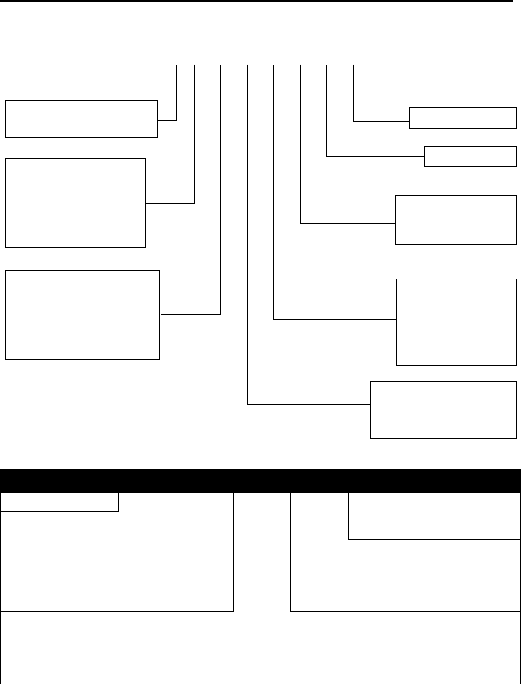
'(/(4+*"&-.4<-*">)2<+4(-.
!"#$%&'(&
'(/(4+*"&-.4<-*"5+.2*
21
!
!"#$%&'()$*+"#,-.)/-+#%01#(20),!"(#$/"#+-,$)"%#$)#)!"#+-2"/#+"3)#!$.%#1-/)0-.#-3#)!"#%040)$+#56$/)#7".)"/8# !"#0.1')(#$/"#-.+9#:0(0*+"#$.%#$,,"((0*+"#20)!#)!"#
3/-.)#,-:"/#/"6-:"%#3/-6#)!"#; <78
!"!#$%&'()#*(%&+,-*&.)/0#&'()1!"0*$#!()
!"#$% &'($)"*#"+, -.,$#"+, -/$#+)01 '##",2 3*#"+,
= >6"/4".,9#?"$)#@:"//0%"#
3-/#;A?#?"$)#;'61#
B-%"+(
>.$*+"(#"+",)/0,#!"$)#-.+9#-1"/$)0-.#0.#)!"#":".)#-3#$#,-6C
1/"((-/#3$0+'/"#-.#?;#6-%"+(8
A-2.#C#D-/6$+#@1"/$)0-. E1#C#@:"//0%"(#,-61/"((-/#-1"/$)0-.8#
F;A?#6-%"+(#-.+9G
H I$++# !"/6-()$)#520),! >.$*+"(#)!"#'("#-3#$#2$++#)!"/6-()$)#-/#'.0)#,-.)/-+( A-2.#C#E.0)#7-.)/-+( E1#C#>.$*+"(#I$++# !"/6-()$)#E($4"
J K$.#79,+"#3-/#?"$)0.4 <++-2(#("+",)0-.#-3#,-.)0.'-'(#3$.#-/#,9,+0.4#0.#!"$)0.4#6-%"8 A-2.#C#79,+" E1#C#7-.)0.'-'(
L K$.#79,+"#3-/#7--+0.4 <++-2(#("+",)0-.#-3#,-.)0.'-'(#3$.#-/#,9,+0.4#0.#,--+0.4#6-%"8 A-2.#C#7-.)0.'-'( E1#C#79,+"
M 5")1-0.)#520),!#= <++-2(#)!"#)"61"/$)'/"#(")1-0.)#/$.4"#)-#*"#$%&'()"%8 A-2. N=KCONK E1 NJKCOPK A-2. NMKCQOK E1 NOKCQMK
N 5")1-0.)#520),!#H A-2. F=N7CJP7G A-2. F=O7CHO7G E1 F=R7CHN7G E1 FHP7CHL7G
Q S--6#K/""T"#;/-)",)0-. <++-2(#)!"#'.0)#)-#".('/"#)!"#0.%--/#/--6#)"61"/$)'/"#%-"(#
.-)#3$++#*"+-2#LPK#":".#2!".#)'/."%#-338
A-2.#C#K/""T"#;/-)",)0-.#>.$*+"% E1#C#K/""T"#;/-)",)0-.#A0($*+"%
FRP028
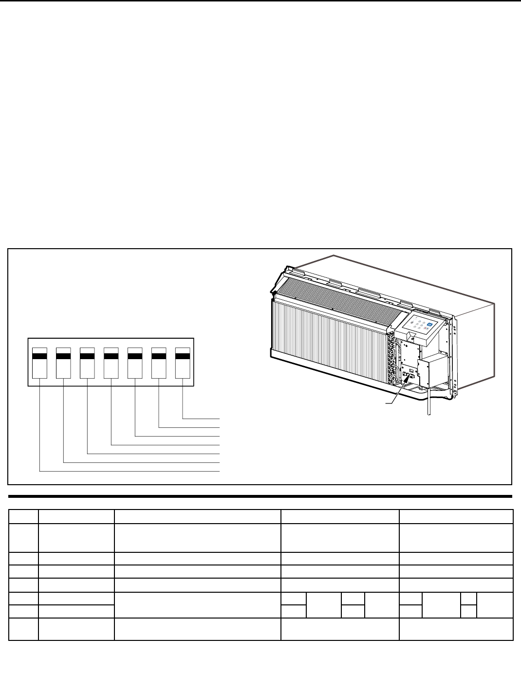
DIP SWITCH
LOCATION OF
DIP SWITCHES
ON UNIT
1 2 3 4 5 6 7
Freeze guard
Setpoint Limit 2
Setpoint Limit 1
Fan CON/CYC for cooling
Fan CON/CYC for heating
Wall Thermostat enable
Electric heat only (for Heat Pumps)
UP
DOWN
High
Med
Lo
w
F
an
Cool
Heat
Fan Speed Mode
Te
mperature
Power
!"#$%&'(&
!/&23!#45-,
451 67')2',$018'/#139'))":'1;1 !"#$%14
U.#)!"#'.+0V"+9#":".)#-3#$#,-61/"((-/#3$0+'/"#$#!"$)#1'61#'.0)#6$9#
*"#(20),!"%#)-#-1"/$)"#0.#-.+9#)!"#"+",)/0,#!"$)#6-%"#'.)0+#/"1$0/(#
,$.#*"#6$%"8#B-:0.4#A01#520),!#=#)-#W@DX8
<51 =/>>1?%')7+(#/#1 !"#$%1<
U.#-/%"/#)-#".$*+"#)!"#2$++#)!"/6-()$)#6-:"#A01#520),!#)-#Y@DY8
@51 -/,1A0$>'1A+,#)+>1;1 !"#$%1@BC
<++#; <7(#$/"#(!011"%#3/-6#)!"#3$,)-/9#20)!#A01#520),!#JCL#0.#
)!"#W@KKX#1-(0)0-.8##U.#)!0(#1-(0)0-.#)!"#,--+0.4#3$.#,9,+"#20++#/'.#
,-.)0.'-'(+9#1/-:0%0.4#$0/#,0/,'+$)0-.#%'/0.4#)!"#2$/6#6-.)!(8##
!"#!"$)0.4#3$.#,9,+"#0(#(")#)-#Y,9,+"Y#-.#$.%#-338## !"#3$.#6$9#
*"#(")#)-#Y,-.)0.'-'(Y#6-%"#*9#(20),!0.4#A01#520),!#J#)-#Y@DY#
1-(0)0-.8
C51 6>'$#)+,"$1?'7*')/#.)'1D"7"#",21;1 !"#$%'(1EBF
!"#%040)$+#,-.)/-+#0(#(")#3/-6#)!"#3$,)-/9#)-#$++-2#$#)"61"/$)'/"#
/$.4"#*")2"".#N=Z#K#$.%#ONZ#K#0.#*-)!#!"$)0.4#$.%#,--+0.4#
6-%"8#A01#520),!"(#MCN#,$.#*"#'("%#)-#(")#!04!#$.%#+-2#+060)(#3-/#
"0)!"/#!"$)0.4#*-)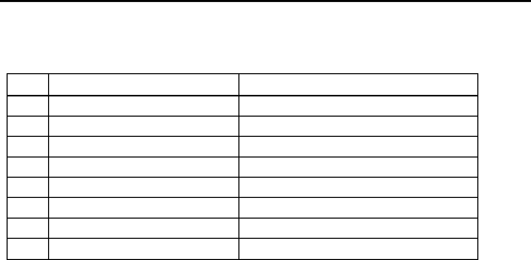
DIGITAL CONTROL DIAGNOSTICS
The chart below lists malfunctions and their description.
Indoor air temp sensor open/short
Indoor coil sensor open or short
Outdoor coil sensor open/short
Freeze Guard protection
Indoor coil high temp protection
Outdoor coil high temp protection
Indoor coil freeze protection
Defrost (heat pump type)
Thermostat wiring error
Display ‘F1’, with STATUS light flash
Display ‘F2’, with STATUS light flash
Display ‘F4’, with STATUS light flash
Display ‘FP’, with STATUS light flash
STATUS light flash 8 times and off 3 sec, repeat
STATUS light flash 6 times and off 3 sec, repeat
STATUS light flash 5 times and off 3 sec, repeat
STATUS light flash 7 times and off 3 sec, repeat
STATUS light flash 9 times and off 3 sec, repeat
1
2
3
4
5
6
7
8
9
23
24
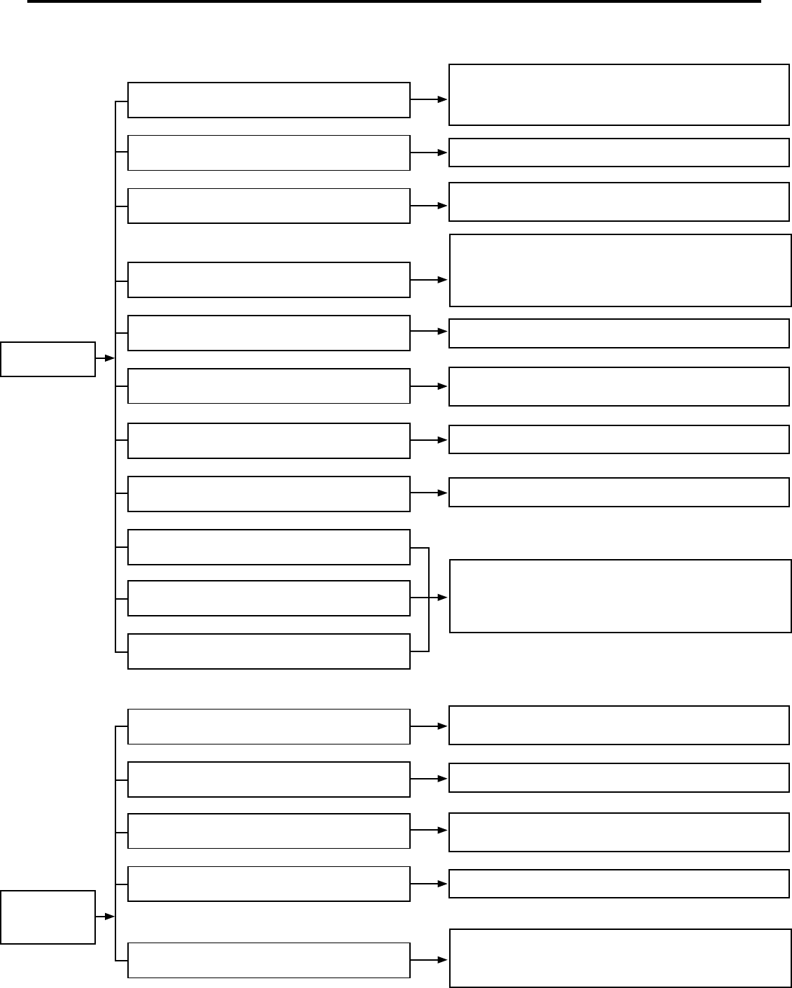
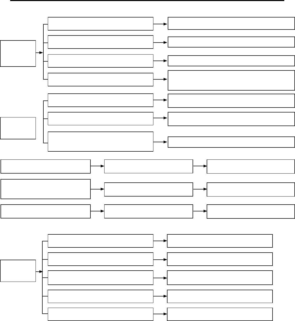
MALFUNCTION ANALYSIS
Switch is broken down
Transformer is broken
Fuse is burned out
No power supply
Failure of crystal oscillator or reset circuit
Controller is broken
The thermostat hasn’t been adjusted well
Receiver head is broken or it isn’t plugged well
Heat exchanger is blocked
Supply voltage is too low
The wire is loosened
A/C can’t run
A/C can run but
it can’t cooling
(or heating)
Receiver head is loosened
Too much dust accumulated on the fi lter
Remote controller has malfunction
Fan speed is set too slow
The fan can’t run or the fan speed is too slow
Switch is at the OFF position; or socket and plug is
loosened; or power wire has malfunction; or power failure
Inspect the supply voltage. If it is lower 10% of the rated
voltage, pleaselook for the reason, improve the
Check the circuit and connect the wire according to the
electric diagram attached to the unit
Lower the temperature of the thermostat
(or increase the temperature when heating)
Clean the dust accumulated on the surface of the heat
exchanger
Check if optional switch (ON,OFF) is disconnected with the
wire or it’s with mechanical failure; use the universal meter to
check if contacts of the switch are conducting; if not, replace
it with a new one with the same model and specifi cation
First press the “AUTO” button of the manual switch. If the
button is normal, recheck if the installation and connection of
head and lines are correct. If correct, replace receiving head
or remote controller.
1. Wrong wire connection; 2. whether the capacitor
damaged or not; 3. the motor has malfunction; Connect the
wire correctly or replace those parts which has malfunction.
Replace the fuse
Replace the transformer
Replace the controller
Clean the fi lter
Set the fan speed at high or medium fan speed
Replace those parts which have malfunction

25
The effi ciency of the compressor is low
Whether the cooling (heating) load is suitable
Refrigeration system is blocked
Refrigerant is insuffi cient or leaking
Condenser can’t discharge smoothly
The air tightness in room is not good. People
come in and go out frequently. There are
heating devices in the room when A/C is cooling
The fan’s capacitor is broken
The controller has malfunction
The compressor’s motor is burned out
Supply voltage is unstable
Too much refrigerant
Outdoor temperature is too high
At the time of heating, the electric heater
can’t run
Compressor
isn’t running
(controller is
with output)
Call for fan
motor but fan
motor will not
come on
A/C on. No
cooling (or
heating)
The motor winding is of broken circuit or short
circuit or the built in temperature limiter device
in open circuit due to overheat.
Wrong wire connection
The compressor capacitor is broken; wrong wire
connection
The compressor is jammed or blocked
Check leakage, carry out vacuum-pumping after repairing
leakage and charge refrigerant according to requirements
You can install the rain-proof and sun-proof board. If the
cooling air is still insuffi cient, you are suggested
to replace the A/C
1. the wire is loosened; 2. thermal fuse is broken;
3. temperature limiter is damaged; 4. electric heater is
damaged; 5. controller is broken. correct the wore correctly
or replace those parts which has malfunction.
Replace fan’s capacitor with the same
mode and specifi cation
Check the circuit and connect the wire correctly
according to the electic circuit diagram
Replace the controller
Keep the air tightness well. Try not to use the electic
appliances with a large quantity of heat
Check with a multimeter if the enclosed motor windings of
compressor is with short or broken circuit or earthing. If so, it
is needed to replace it with the same type and specifi cations.
Knock the compressor housing with a rubber bar or with
a hammer padding with a wood, the compressor might be
shocked and run. If not, change the compressor.
Check whether the system is blocked by observing the
condensation of the evaporator and the pressure value of
the high pressure manometer, and then take measures to
deal with the system.
Check the preset cooling (heating) load
Check the reason and correct it.
Replace those parts which has malfunction
Replace capacitor; connect the wire correctly
according to the electric circuit diagram
Get rid of the obstacle
Replace the compressor
Release the redundant refrigerant in system
26
Protector has malfunction
Reveiving distance of remote control
is too short
LED display is found short of stroke
LCD display fl ashes or when pressing
the transmit button the entire screen
is displayed.
Replace the battery
Fix the LCD frame properly
Replace the battery
Replace the battery
The LCD frame hasn’t fi xed well
Battery’s capacity is insuffi cient
Capillary is blocked and the suction
temperature is rising
Refrigerant is insuffi cient or super abundance
Supply voltage is abnormal
The unit hasn’t placed fl atly and stable Adjust the unit’s position
There are foreign objects on the unit Get rid of the foreign objects
Screws are loosened Tighten the screws
The compressor can run smoothly or is stuck.
The air discharge valve is damaged.
The air conditioner capability does not match
the area of the room, i.e. so called “Big system,
small room”.
The radiating for evaporator and condensor is
not good; Poor air ventilation
Compressor
is ON-OFF
frequently
Vibration and
noise are
abnormal
Protector is
activated due to
overheating of
the compressor
The unit’s support is unstable Strengthen the support or refi t it
The compressor hasn’t installed well and the
base is unstable
Check whether the base is fi rm
Adjust the quantity of the refrigerant
Check the reason, improve the power supply condition and
add the regulated power supply
Get rid of the dust on the evaporator and condensor, remove
the obstacles at the air outlet
Use the multimeter to check whether the contact point of the
compressor is conducted at the timer of non-subheating. If it
can’t be conducted, please replace the protector.
Replace the compressor
Slect the A/C which is applicable to the room areas
Replace capillary
As for the above malfunction analysis, there aren’t malfunction related to heating for the cooling only unit.
27
CAPACITORS
ELECTRIC SHOCK HAZARD
WARNING
Turn off electric power before servicing.
Discharge capacitor with a 20,000 Ohm 2 Watt
resistor before handling.
Failure to do so may result in personal injury,
or death.
Capacitor Check with Capacitor Analyzer
The capacitor analyzer will show whether the capacitor
is “open” or “shorted.” It will tell whether the capacitor
is within its micro farads rating and it will show whether
the capacitor is operating at the proper power-factor
percentage. The instrument will automatically discharge
the capacitor when the test switch is released.
Capacitor Connections
The starting winding of a motor can be damaged by a
shorted and grounded running capacitor. This damage
usually can be avoided by proper connection of the running
capacitor terminals.
From the supply line on a typical 230 volt circuit, a 115 volt
potential exists from the “R” terminal to ground through a
possible short in the capacitor. However, from the “S” or start
terminal, a much higher potential, possibly as high as 400
volts, exists because of the counter EMF generated in the
start winding. Therefore, the possibility of capacitor failure
is much greater when the identifi ed terminal is connected
to the “S” or start terminal. The identifi ed terminal should
always be connected to the supply line, or “R” terminal,
never to the “S” terminal.
When connected properly, a shorted or grounded running
capacitor will result in a direct short to ground from the “R”
terminal and will blow the line fuse. The motor protector
will protect the main winding from excessive temperature.
COMPONENTS TESTING
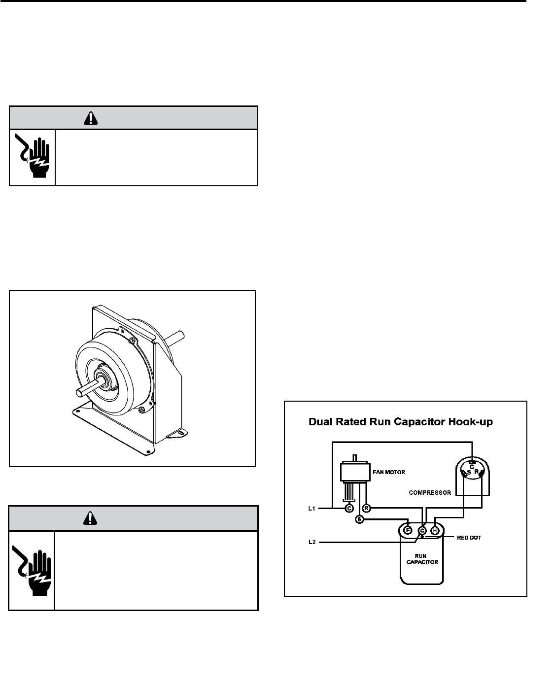
BLOWER / FAN MOTOR TEST
BLOWER / FAN MOTOR
A single phase permanent split capacitor motor is used to drive
the evaporator blower and condenser fan. A self-resetting
overload is located inside the motor to protect against high
temperature and high amperage conditions.
ELECTRIC SHOCK HAZARD
WARNING
Disconnect power to the unit before
servicing. Failure to follow this warning
could result in serious injury or death.
1. Make sure the motor has cooled down.
2. Disconnect the fan motor wires from the control board.
3. Test for continuity between the windings also, test to
ground.
4. If any winding is open or grounded replace the motor.
Many motor capacitors are internally fused. Shorting the
terminals will blow the fuse, ruining the capacitor. A 20,000
ohm 2 watt resistor can be used to discharge capacitors
safely. Remove wires from capacitor and place resistor
across terminals. When checking a dual capacitor with
a capacitor analyzer or ohmmeter, both sides must be
tested.
28
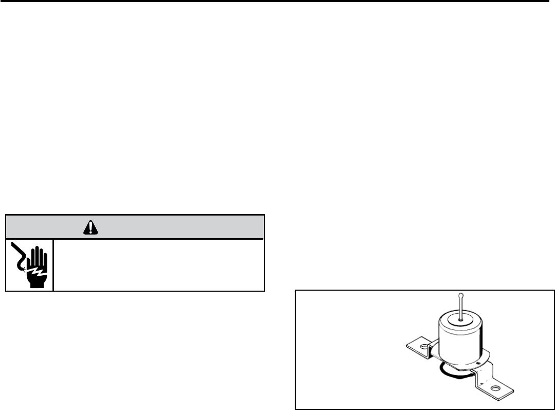
DRAIN PAN VALVE
During the cooling mode of operation, condensate which
collects in the drain pan is picked up by the condenser fan
blade and sprayed onto the condenser coil. This assists
in cooling the refrigerant plus evaporating the water.
During the heating mode of operation, it is necessary that
water be removed to prevent it from freezing during cold
outside temperatures. This could cause the condenser
fan blade to freeze in the accumulated water and prevent
it from turning.
To provide a means of draining this water, a bellows type
drain valve is installed over a drain opening in the base
pan.
This valve is temperature sensitive and will open when
the outside temperature reaches 40°F. The valve will
close gradually as the temperature rises above 40°F to
fully close at 60°F.
TESTING THE HEATING ELEMENTS AND
LIMIT SWITCHES
Testing of the heating elements can be made with an
ohmmeter or continuity tester across the terminals after
the power wires have been removed. Test the limit switch
for continuity across its input and output terminals.Test
below the limit switch’s reset temperature.
HEATER ELEMENTS AND LIMIT SWITCHES’
SPECIFICATIONS
All heat pumps and electric heat models are equipped
with a heating element and a limit switch (bimetal ther-
mostat). The limit is in series with the element and will
interrupt the power at a designed temperature.
Should the blower motor fail, fi lter become clogged or air-
fl ow be restricted etc., the high limit switch will open and
interrupt the power to the heater before reaching an un-
safe temperature condition.
Bellows Assembly
Drain Pan Valve
COMPONENTS TESTING (Continued)
ELECTRIC SHOCK HAZARD
WARNING
Disconnect power to the unit before
servicing. Failure to follow this warning
could result in serious injury or death.
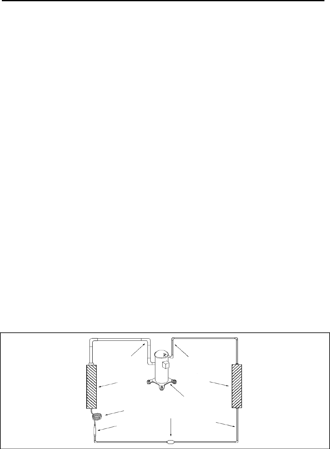
Suction
Line
Evaporator
Coil
Metering
Device
Refrigerant
Strainer
Discharge
Line
Condenser
Coil
Compressor
Refrigerant Drier
Liquid
Line
A good understanding of the basic operation of the
refrigeration system is essential for the service technician.
Without this understanding, accurate troubleshooting of
refrigeration system problems will be more diffi cult and time
consuming, if not (in some cases) entirely impossible. The
refrigeration system uses four basic principles (laws) in its
operation they are as follows:
1. “Heat always fl ows from a warmer body to a cooler
body.”
2. “Heat must be added to or removed from a substance
before a change in state can occur”
3. “Flow is always from a higher pressure area to a lower
pressure area.”
4. “The temperature at which a liquid or gas changes state
is dependent upon the pressure.”
The refrigeration cycle begins at the compressor. Starting
the compressor creates a low pressure in the suction line
which draws refrigerant gas (vapor) into the compressor.
The compressor then “compresses” this refrigerant, raising
its pressure and its (heat intensity) temperature.
The refrigerant leaves the compressor through the discharge
Line as a hot High pressure gas (vapor). The refrigerant
enters the condenser coil where it gives up some of its
heat. The condenser fan moving air across the coil’s fi nned
surface facilitates the transfer of heat from the refrigerant to
the relatively cooler outdoor air.
When a suffi cient quantity of heat has been removed from
the refrigerant gas (vapor), the refrigerant will “condense”
(i.e. change to a liquid). Once the refrigerant has been
condensed (changed) to a liquid it is cooled even further by
the air that continues to fl ow across the condenser coil.
The PTAC design determines at exactly what point (in
the condenser) the change of state (i.e. gas to a liquid)
takes place. In all cases, however, the refrigerant must be
totally condensed (changed) to a Liquid before leaving the
condenser coil.
The refrigerant leaves the condenser Coil through the liquid
line as a warm high pressure liquid. It next will pass through
the refrigerant drier (if so equipped). It is the function of the
drier to trap any moisture present in the system, contaminants,
and large particulate matter.
The liquid refrigerant next enters the metering device. The
metering device is a capillary tube. The purpose of the
metering device is to “meter” (i.e. control or measure) the
quantity of refrigerant entering the evaporator coil.
In the case of the capillary tube this is accomplished (by
design) through size (and length) of device, and the pressure
difference present across the device.
Since the evaporator coil is under a lower pressure (due to
the suction created by the compressor) than the liquid line,
the liquid refrigerant leaves the metering device entering the
evaporator coil. As it enters the evaporator coil, the larger
area and lower pressure allows the refrigerant to expand
and lower its temperature (heat intensity). This expansion is
often referred to as “boiling”. Since the unit’s blower is moving
indoor air across the fi nned surface of the evaporator coil,
the expanding refrigerant absorbs some of that heat. This
results in a lowering of the indoor air temperature, hence the
“cooling” effect.
The expansion and absorbing of heat cause the liquid
refrigerant to evaporate (i.e. change to a gas). Once the
refrigerant has been evaporated (changed to a gas), it is
heated even further by the air that continues to fl ow across
the evaporator coil.
The particular system design determines at exactly what
point (in the evaporator) the change of state (i.e. liquid to a
gas) takes place. In all cases, however, the refrigerant must
be totally evaporated (changed) to a gas before leaving the
evaporator coil.
The low pressure (suction) created by the compressor
causes the refrigerant to leave the evaporator through the
suction line as a cool low pressure vapor. The refrigerant then
returns to the compressor, where the cycle is repeated.
29
REFRIGERATION SEQUENCE OF OPERATION
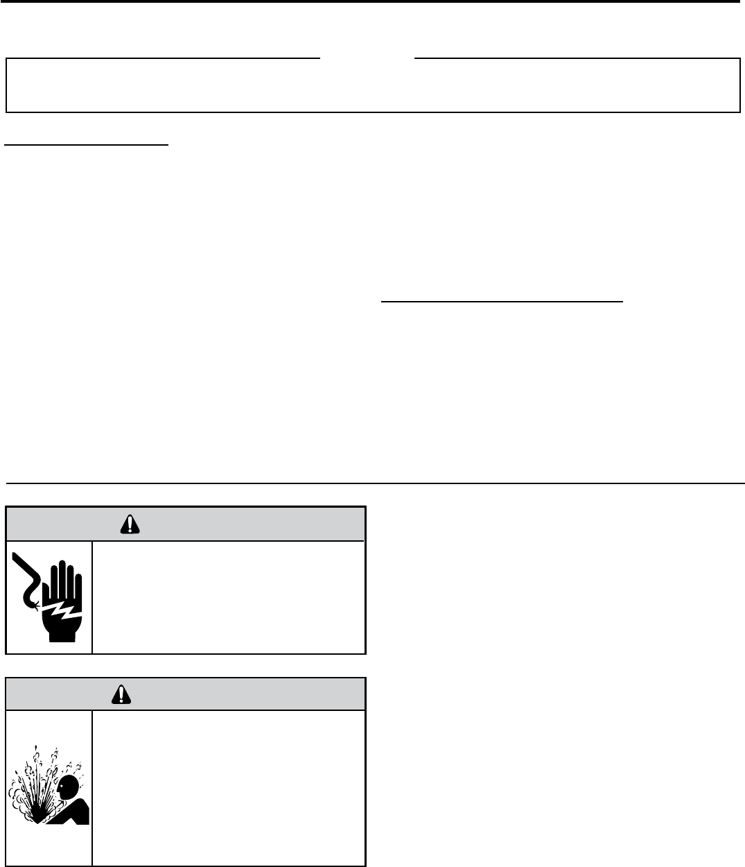
30
Refrigerant Charging
Proper refrigerant charge is essential to proper unit opera-
tion. Operating a unit with an improper refrigerant charge will
result in reduced performance (capacity) and/or effi ciency.
Accordingly, the use of proper charging methods during ser-
vicing will insure that the unit is functioning as designed and
that its compressor will not be damaged.
Too much refrigerant (overcharge) in the system is just as bad
(if not worse) than not enough refrigerant (undercharge). They
both can be the source of certain compressor failures if they
remain uncorrected for any period of time. Quite often, other
problems (such as low air fl ow across evaporator, etc.) are
misdiagnosed as refrigerant charge problems. The refrigerant
circuit diagnosis chart will assist you in properly diagnosing
these systems.
An overcharged unit will at times return liquid refrigerant
(slugging) back to the suction side of the compressor eventually
causing a mechanical failure within the compressor. This
mechanical failure can manifest itself as valve failure, bearing
failure, and/or other mechanical failure. The specifi c type of
failure will be infl uenced by the amount of liquid being returned,
and the length of time the slugging continues.
Not enough refrigerant (undercharge) on the other hand, will
cause the temperature of the suction gas to increase to the point
where it does not provide suffi cient cooling for the compressor
motor. When this occurs, the motor winding temperature will
increase causing the motor to overheat and possibly cycle open
the compressor overload protector. Continued overheating of
the motor windings and/or cycling of the overload will eventually
lead to compressor motor or overload failure.
Unplug and/or disconnect all electrical power
to the unit before performing inspections,
maintenances or service.
Failure to do so could result in electric shock,
serious injury or death.
Sealed Refrigeration System contains refrigerant
and oil under high pressure.
Proper safety procedures must be followed,
and proper protective clothing must be worn
when working with refrigerants.
Failure to follow these procedures could
result in serious injury or death.
WARNING
WARNING
RISK OF ELECTRIC SHOCK
HIGH PRESSURE HAZARD
R-410A SEALED REFRIGERATION SYSTEM REPAIRS
SEALED SYSTEM REPAIRS TO COOL-ONLY MODELS REQUIRE THE INSTALLATION OF A LIQUID LINE DRIER.
SEALED SYSTEM REPAIRS TO HEAT PUMP MODELS REQUIRE THE INSTALLATION OF A SUCTION LINE DRIER.
IMPORTANT
EQUIPMENT REQUIRED:
1. Voltmeter
2. Ammeter
3. Ohmmeter
4. E.P.A. Approved Refrigerant Recovery System
5. Vacuum Pump (capable of 200 microns or less
vacuum.)
6. Acetylene Welder
7. Electronic Halogen Leak Detector capable of detect-
ing HFC (Hydrofl uorocarbon) refrigerants.
8. Accurate refrigerant charge measuring device such
as:
a. Balance Scales - 1/2 oz. accuracy
b. Charging Board - 1/2 oz. accuracy
9. High Pressure Gauge - (0 - 750 lbs.)
10. Low Pressure Gauge - (30 - 200 lbs.)
11. Vacuum Gauge - (0 - 1000 microns)
12. Facilities for fl owing nitrogen through refrigeration tubing
during all brazing processes.
EQUIPMENT MUST BE CAPABLE OF:
1. Recovering refrigerant to EPA required levels.
2. Evacuation from both the high side and low side of the
system simultaneously.
3. Introducing refrigerant charge into high side of the
system.
4. Accurately weighing the refrigerant charge introduced
into the system.
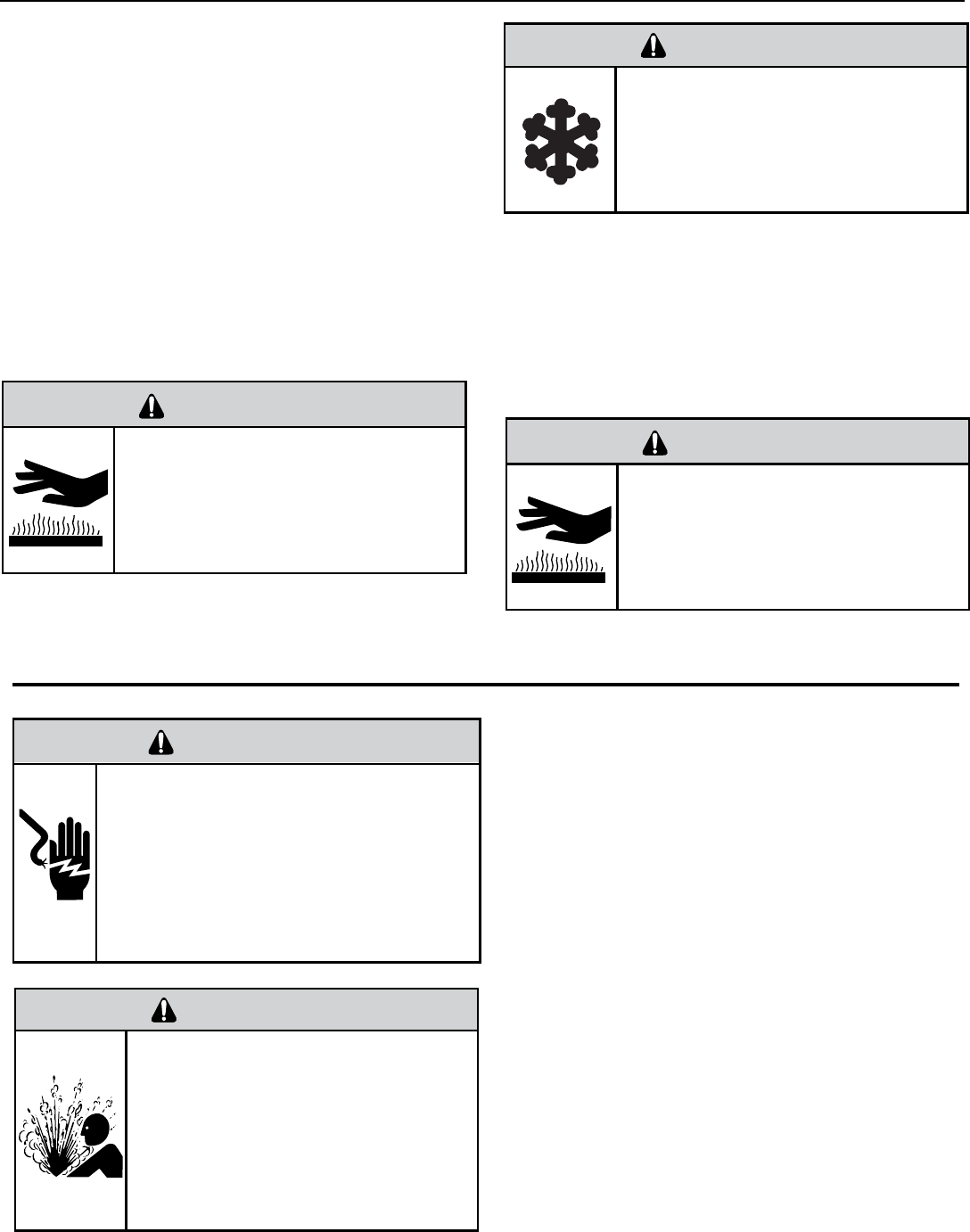
31
3. Install a process tube to sealed system.
4. Make necessary repairs to system.
5. Evacuate system to 200 microns or less.
6. Weigh in refrigerant with the property quantity of R-410A
refrigerant.
7. Start unit, and verify performance.
8. Crimp the process tube and solder the end shut.
Proper safety procedures must be followed,
and proper protective clothing must be worn
when working with a torch.
Failure to follow these procedures could
result in moderate or serious injury.
Proper safety procedures must be followed,
and proper protective clothing must be worn
when working with liquid refrigerant.
Failure to follow these procedures could
result in minor to moderate injury.
WARNING
CAUTION
BURN HAZARD
FREEZE HAZARD
Proper safety procedures must be followed,
and proper protective clothing must be worn
when working with a torch.
Failure to follow these procedures could
result in moderate or serious injury.
WARNING
BURN HAZARD
Method Of Charging / Repairs
The acceptable method for charging the RAC system is the
Weighed in Charge Method. The weighed in charge method is
applicable to all units. It is the preferred method to use, as it is
the most accurate.
The weighed in method should always be used whenever
a charge is removed from a unit such as for a leak repair,
compressor replacement, or when there is no refrigerant
charge left in the unit. To charge by this method, requires the
following steps:
1. Install a piercing valve to remove refrigerant from the
sealedsystem. (Piercing valve must be removed from the
system before recharging.)
2. Recover Refrigerant in accordance with EPA regulations.
ELECTRIC SHOCK HAZARD
WARNING
Turn off electric power before service or
installation.
Extreme care must be used, if it becomes
necessary to work on equipment with power
applied.
Failure to do so could result in serious injury or
death.
Sealed Refrigeration System contains refrigerant
and oil under high pressure.
Proper safety procedures must be followed,
and proper protective clothing must be worn
when working with refrigerants.
Failure to follow these procedures could
result in serious injury or death.
WARNING
HIGH PRESSURE HAZARD
Undercharged Refrigerant Systems
An undercharged system will result in poor performance
(low pressures, etc.) in both the heating and cooling
cycle.
Whenever you service a unit with an undercharge of
refrigerant, always suspect a leak. The leak must be
repaired before charging the unit.
To check for an undercharged system, turn the unit on,
allow the compressor to run long enough to establish
working pressures in the system (15 to 20 minutes).
During the cooling cycle you can listen carefully at the exit
of the metering device into the evaporator; an intermittent
hissing and gurgling sound indicates a low refrigerant
charge. Intermittent frosting and thawing of the evaporator
is another indication of a low charge, however, frosting
and thawing can also be caused by insuffi cient air over
the evaporator.
Checks for an undercharged system can be made at
the compressor. If the compressor seems quieter than
normal, it is an indication of a low refrigerant charge.
A check of the amperage drawn by the compressor
motor should show a lower reading. (Check the Unit
Specifi cation.)
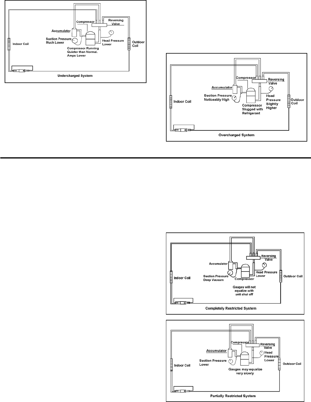
32
Overcharged Refrigerant Systems
After the unit has run 10 to 15 minutes, check the gauge
pressures. Gauges connected to system with an undercharge
will have low head pressures and substantially low suction
pressures.
Improper air fl ow over the evaporator coil may indicate
some of the same symptoms as an over charged system.
An overcharge can cause the compressor to fail, since it
would be “slugged” with liquid refrigerant.
The charge for any system is critical. When the compressor
is noisy, suspect an overcharge, when you are sure that the
air quantity over the evaporator coil is correct. Icing of the
evaporator will not be encountered because the refrigerant
will boil later if at all. Gauges connected to system will usually
have higher head pressure (depending upon amount of over
charge). Suction pressure should be slightly higher.
Compressor amps will be near normal or higher.
Noncondensables can also cause these symptoms. To
confi rm, remove some of the charge, if conditions improve,
system may be overcharged. If conditions don’t improve,
Noncondensables are indicated.
Whenever an overcharged system is indicated, always make
sure that the problem is not caused by air fl ow problems.
Restricted Refrigerant System
Troubleshooting a restricted refrigerant system can be
diffi cult. The following procedures are the more common
problems and solutions to these problems. There are two
types of refrigerant restrictions: Partial restrictions and
complete restrictions.
A partial restriction allows some of the refrigerant to
circulate through the system.
With a complete restriction there is no circulation of
refrigerant in the system.
Restricted refrigerant systems display the same symptoms
as a “low-charge condition.”
When the unit is shut off, the gauges may equalize very
slowly.
Gauges connected to a completely restricted system will
run in a deep vacuum. When the unit is shut off, the gauges
will not equalize at all.
A quick check for either condition begins at the evaporator.
With a partial restriction, there may be gurgling sounds
at the metering device entrance to the evaporator. The
evaporator in a partial restriction could be partially frosted
or have an ice ball close to the entrance of the metering
device. Frost may continue on the suction line back to the
compressor.
Often a partial restriction of any type can be found by feel,
as there is a temperature difference from one side of the
restriction to the other.
With a complete restriction, there will be no sound at the
metering device entrance. An amperage check of the
compressor with a partial restriction may show normal
current when compared to the unit specifi cation.
With a complete restriction the current drawn may be
considerably less than normal, as the compressor is
running in a deep vacuum (no load.) Much of the area of
the condenser will be relatively cool since most or all of the
liquid refrigerant will be stored there.
The following conditions are based primarily on a system
in the cooling mode.
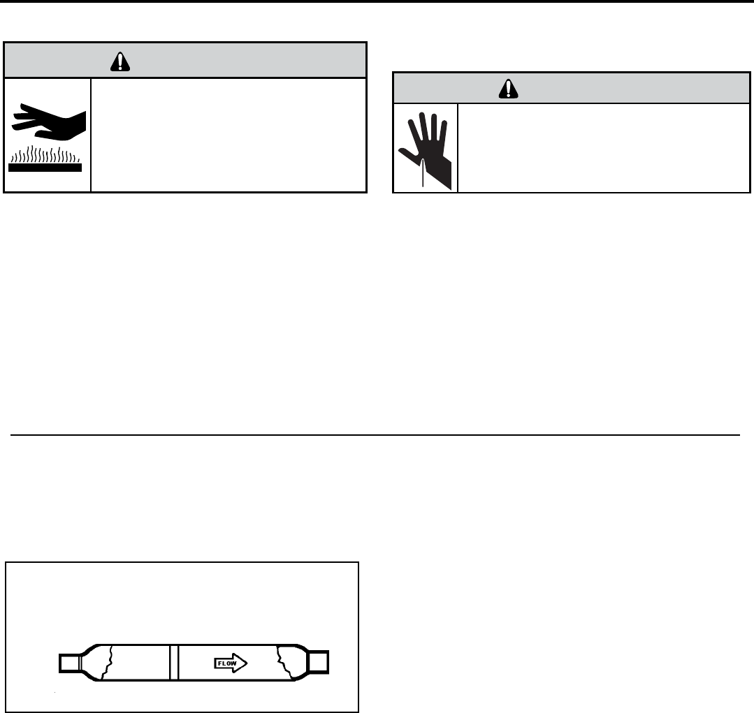
METERING DEVICE
Capillary Tube Systems
All units are equipped with capillary tube metering
devices.
Checking for restricted capillary tubes.
1. Connect pressure gauges to unit.
2. Start the unit in the cooling mode. If after a few minutes
of operation the pressures are normal, the check valve
and the cooling capillary are not restricted.
3. Switch the unit to the heating mode and observe the
gauge readings after a few minutes running time. If
the system pressure is lower than normal, the heating
capillary is restricted.
4. If the operating pressures are lower than normal in both
the heating and cooling mode, the cooling capillary is
restricted.
Proper safety procedures must be followed,
and proper protective clothing must be worn
when working with a torch.
Failure to follow these procedures could
result in moderate or serious injury.
WARNING
BURN HAZARD
HERMETIC COMPONENTS CHECK
One-way Check Valve
(Heat Pump Models)
CHECK VALVE
A unique two-way check valve is used on the reverse cycle
heat pumps. It is pressure operated and used to direct the
fl ow of refrigerant through a single fi lter drier and to the
proper capillary tube during either the heating or cooling
cycle.
NOTE: The slide (check) inside the valve is made of tefl on.
Should it become necessary to replace the check valve,
place a wet cloth around the valve to prevent overheating
during the brazing operation.
CHECK VALVE OPERATION
In the cooling mode of operation, high pressure liquid enters
the check valve forcing the slide to close the opposite port
(liquid line) to the indoor coil. Refer to refrigerant fl ow chart.
This directs the refrigerant through the fi lter drier and cooling
capillary tube to the indoor coil.
In the heating mode of operation, high pressure refrigerant
enters the check valve from the opposite direction, closing
the port (liquid line) to the outdoor coil. The fl ow path of
the refrigerant is then through the fi lter drier and heating
capillary to the outdoor coil.
Failure of the slide in the check valve to seat properly in
either mode of operation will cause fl ooding of the cooling
coil. This is due to the refrigerant bypassing the heating or
cooling capillary tube and entering the liquid line.
COOLING MODE
In the cooling mode of operation, liquid refrigerant from
condenser (liquid line) enters the cooling check valve
forcing the heating check valve shut. The liquid refrigerant
is directed into the liquid dryer after which the refrigerant
is metered through cooling capillary tubes to evaporator.
(Note: liquid refrigerant will also be directed through the
heating capillary tubes in a continuous loop during the
cooling mode).
HEATING MODE
In the heating mode of operation, liquid refrigerant from
the indoor coil enters the heating check valve forcing the
cooling check valve shut. The liquid refrigerant is directed
into the liquid dryer after which the refrigerant is metered
through the heating capillary tubes to outdoor coils. (Note:
liquid refrigerant will also be directed through the cooling
capillary tubes in a continuous loop during the heating
mode).
CUT/SEVER HAZARD
WARNING
Be careful with the sharp edges and corners.
Wear protective clothing and gloves, etc.
Failure to do so could result in serious injury.
33
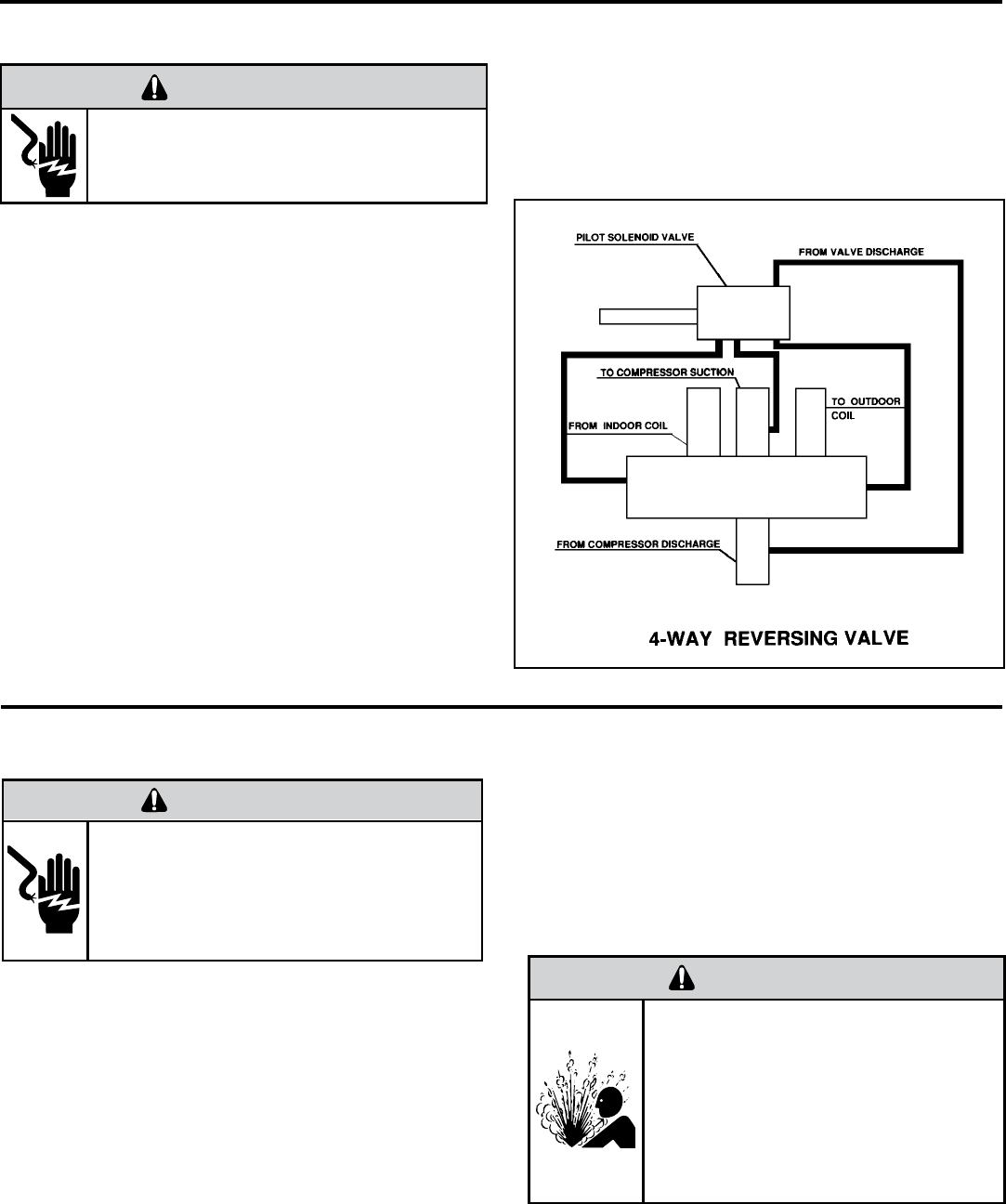
NOTE: System operating pressures must be near
normal before valve can shift.
REVERSING VALVE DESCRIPTION/OPERATION
The Reversing Valve controls the direction of refrigerant fl ow
to the indoor and outdoor coils. It consists of a pressure-
operated, main valve and a pilot valve actuated by a solenoid
plunger. The solenoid is energized during the heating cycle
only. The reversing valves used in the PTAC system is a
2-position, 4-way valve.
The single tube on one side of the main valve body is the
high-pressure inlet to the valve from the compressor. The
center tube on the opposite side is connected to the low
pressure (suction) side of the system. The other two are
connected to the indoor and outdoor coils. Small capillary
tubes connect each end of the main valve cylinder to the “A”
and “B” ports of the pilot valve. A third capillary is a common
return line from these ports to the suction tube on the main
valve body. Four-way reversing valves also have a capillary
tube from the compressor discharge tube to the pilot valve.
The piston assembly in the main valve can only be shifted
by the pressure differential between the high and low sides
of the system. The pilot section of the valve opens and
closes ports for the small capillary tubes to the main valve
to cause it to shift.
ELECTRIC SHOCK HAZARD
WARNING
Disconnect power to the unit before servicing.
Failure to follow this warning could result in
serious injury or death.
TESTING THE COIL
The solenoid coil is an electromagnetic type coil mounted
on the reversing valve and is energized during the
operation of the compressor in the heating cycle.
1. Turn off high voltage electrical power to unit.
2. Unplug line voltage lead from reversing valve coil.
3. Check for electrical continuity through the coil. If you
do not have continuity replace the coil.
4. Check from each lead of coil to the copper liquid line
as it leaves the unit or the ground lug. There should
be no continuity between either of the coil leads
and ground; if there is, coil is grounded and must be
replaced.
5. If coil tests okay, reconnect the electrical leads.
6. Make sure coil has been assembled correctly.
ELECTRIC SHOCK HAZARD
WARNING
Unplug and/or disconnect all electrical power
to the unit before performing inspections,
maintenances or service.
Failure to do so could result in electric shock,
serious injury or death.
NOTE: Do not start unit with solenoid coil removed from
valve, or do not remove coil after unit is in operation. This
will cause the coil to burn out.
CHECKING THE REVERSING VALVE
NOTE: You must have normal operating pressures before
the reversing valve can shift.
Check the operation of the valve by starting the system
and switching the operation from “Cooling” to “Heating”
and then back to “Cooling”. Do not hammer on valve.
Occasionally, the reversing valve may stick in the heating
or cooling position or in the mid-position.
Sealed Refrigeration System contains refrigerant
and oil under high pressure.
Proper safety procedures must be followed,
and proper protective clothing must be worn
when working with refrigerants.
Failure to follow these procedures could
result in serious injury or death.
WARNING
HIGH PRESSURE HAZARD
34
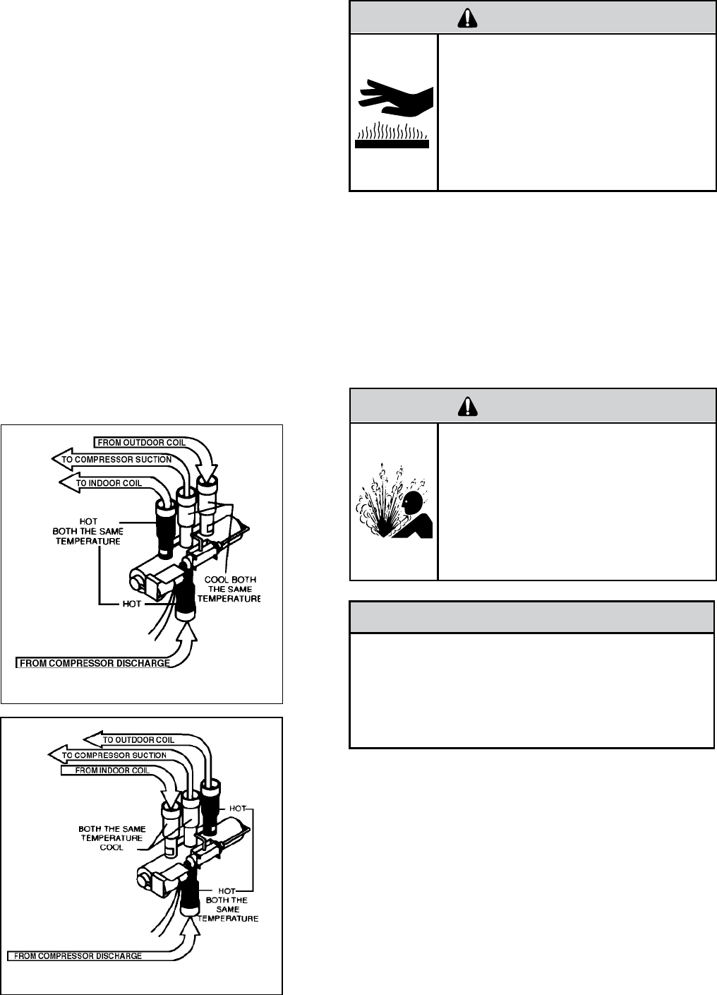
Reversing Valve in Heating Mode
When sluggish or stuck in the mid-position, part of the
discharge gas from the compressor is directed back to the
suction side, resulting in excessively high suction pressure.
Should the valve fail to shift from coooling to heating,
block the air fl ow through the outdoor coil and allow the
discharge pressure to build in the system. Then switch the
system from heating to cooling.
If the valve is stuck in the heating position, block the air
fl ow through the indoor coil and allow discharge pressure
to build in the system. Then switch the system from heating
to cooling.
Should the valve fail to shift in either position after increasing
the discharge pressure, replace the valve.
Dented or damaged valve body or capillary tubes can
prevent the main slide in the valve body from shifting.
If you determing this is the problem, replace the reversing
valve.
After all of the previous inspections and checks have been
made and determined correct, then perform the “Touch
Test” on the reversing valve.
Reversing Valve in Cooling Mode
Procedure For Changing Reversing Valve
1. Install Process Tubes. Recover refrigerant from sealed
system. PROPER HANDLING OF RECOVERED
REFRIGERANT ACCORDING TO EPA REGULATIONS
IS REQUIRED.
2. Remove solenoid coil from reversing valve. If coil is to
be reused, protect from heat while changing valve.
3. Unbraze all lines from reversing valve.
4. Clean all excess braze from all tubing so that they will
slip into fi ttings on new valve.
5. Remove solenoid coil from new valve.
The use of a torch requires extreme care and proper
judgment. Follow all safety recommended precautions
and protect surrounding areas with fi re proof materials.
Have a fi re extinguisher readily available. Failure to follow
this notice could result in moderate to serious property
damage.
NOTICE
FIRE HAZARD
Touch Test in Heating/Cooling Cycle
The only definite indications that the slide is in the mid-
position is if all three tubes on the suction side of the valve
are hot after a few minutes of running time.
NOTE: A condition other than those illustrated above, and
on Page 31, indicate that the reversing valve is not shifting
properly. Both tubes shown as hot or cool must be the same
corresponding temperature.
Certain unit components operate at
temperatures hot enough to cause burns.
Proper safety procedures must be followed,
and proper protective clothing must be
worn.
Failure to follow these procedures could
result in minor to moderate injury.
WARNING
BURN HAZARD
Sealed Refrigeration System contains refrigerant
and oil under high pressure.
Proper safety procedures must be followed,
and proper protective clothing must be worn
when working with refrigerants.
Failure to follow these procedures could
result in serious injury or death.
WARNING
HIGH PRESSURE HAZARD
35
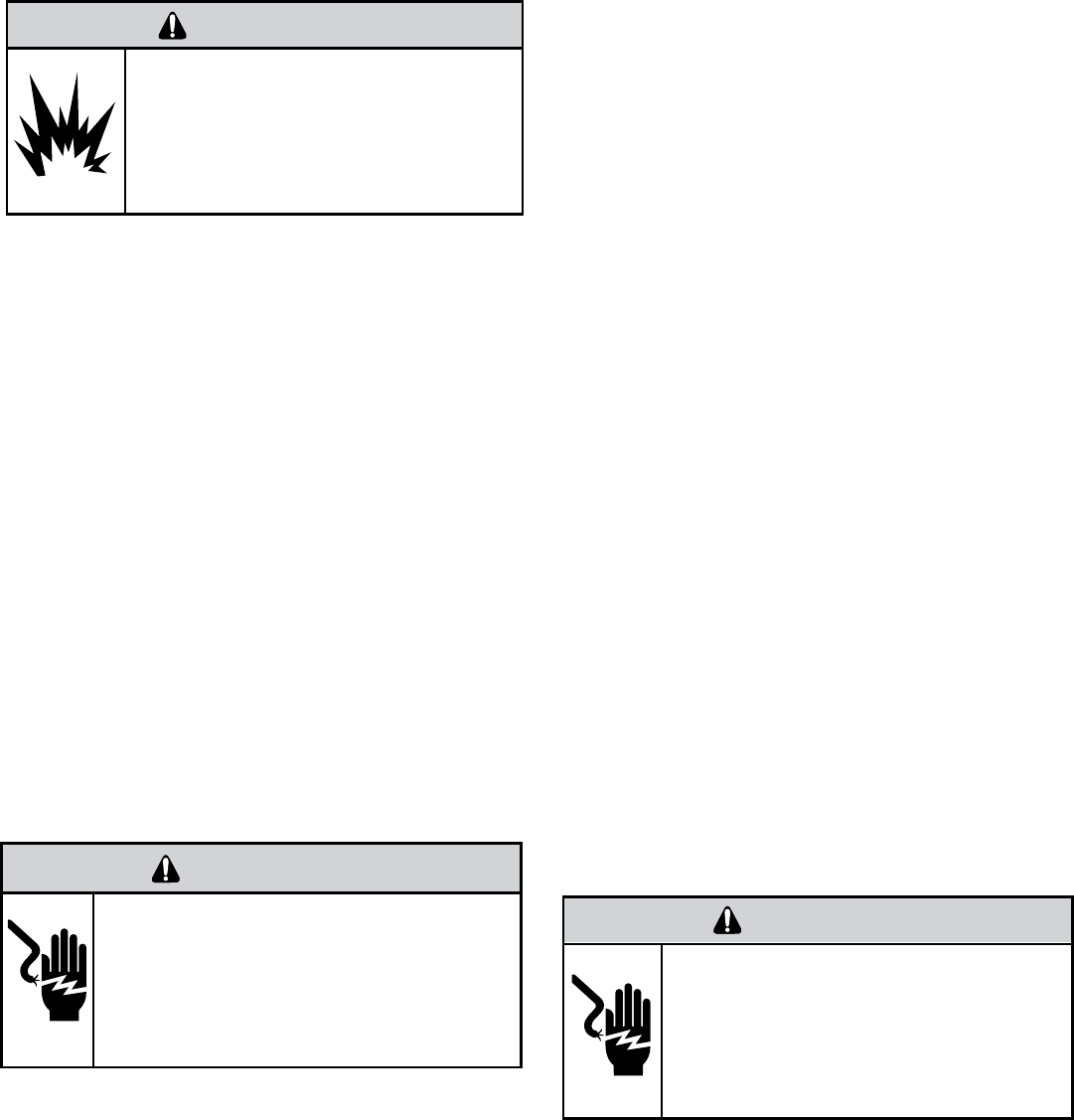
8. Pressurize sealed system with a combination of R-22
and nitrogen and check for leaks, using a suitable leak
detector. Recover refrigerant per EPA guidelines.
9. Once the sealed system is leak free, install solenoid coil
on new valve and charge the sealed system by weighing
in the proper amount and type of refrigerant as shown
on rating plate. Crimp the process tubes and solder the
ends shut. Do not leave Schrader or piercing valves in
the sealed system.
NOTE: When brazing a reversing valve into the system, it is
of extreme importance that the temperature of the valve does
not exceed 250
°F at any time.
Wrap the reversing valve with a large rag saturated with
water. “Re-wet” the rag and thoroughly cool the valve after
each brazing operation of the four joints involved.
The wet rag around the reversing valve will eliminate
conduction of heat to the valve body when brazing the line
connection.
6. Protect new valve body from heat while brazing with plastic
heat sink (Thermo Trap) or wrap valve body with wet
rag.
7. Fit all lines into new valve and braze lines into new
valve.
The use of nitrogen requires a pressure
regulator. Follow all safety procedures and
wear protective safety clothing etc.
Failure to follow proper safety procedures
could result in serious injury or death.
WARNING
EXPLOSION HAZARD
Locked Rotor Voltage (L.R.V.) Test
Locked rotor voltage (L.R.V.) is the actual voltage available
at the compressor under a stalled condition.
Single Phase Connections
Disconnect power from unit. Using a voltmeter, attach one
lead of the meter to the run “R” terminal on the compressor
and the other lead to the common “C” terminal of the com-
pressor. Restore power to unit.
Determine L.R.V.
Start the compressor with the volt meter attached; then stop
the unit. Attempt to restart the compressor within a couple
of seconds and immediately read the voltage on the meter.
The compressor under these conditions will not start and will
usually kick out on overload within a few seconds since the
pressures in the system will not have had time to equalize.
Voltage should be at or above minimum voltage of 197 VAC,
as specifi ed on the rating plate. If less than minimum, check
for cause of inadequate power supply; i.e., incorrect wire
size, loose electrical connections, etc.
Amperage (L.R.A.) Test
The running amperage of the compressor is the most impor-
tant of these readings. A running amperage higher than that
indicated in the performance data indicates that a problem
exists mechanically or electrically.
Single Phase Running and L.R.A. Test
NOTE: Consult the specifi cation and performance section
for running amperage. The L.R.A. can also be found on the
rating plate.
Select the proper amperage scale and clamp the meter
probe around the wire to the “C” terminal of the compressor.
Turn on the unit and read the running amperage on the me-
ter. If the compressor does not start, the reading will indicate
the locked rotor amperage (L.R.A.).
Overloads
The compressor is equipped with an external overload which
senses both motor amperage and winding temperature. High
motor temperature or amperage heats the overload causing it
to open, breaking the common circuit within the compressor.
Heat generated within the compressor shell, usually due to
recycling of the motor, is slow to dissipate. It may take any-
where from a few minutes to several hours for the overload
to reset.
Checking the Overload
COMPRESSOR CHECKS
ELECTRIC SHOCK HAZARD
WARNING
Turn off electric power before service or
installation. Extreme care must be used, if it
becomes necessary to work on equipment with
power applied.
Failure to do so could result in serious injury or
death.
ELECTRIC SHOCK HAZARD
WARNING
Turn off electric power before service or
installation. Extreme care must be used, if it
becomes necessary to work on equipment
with power applied.
Failure to do so could result in serious injury or
death.
36
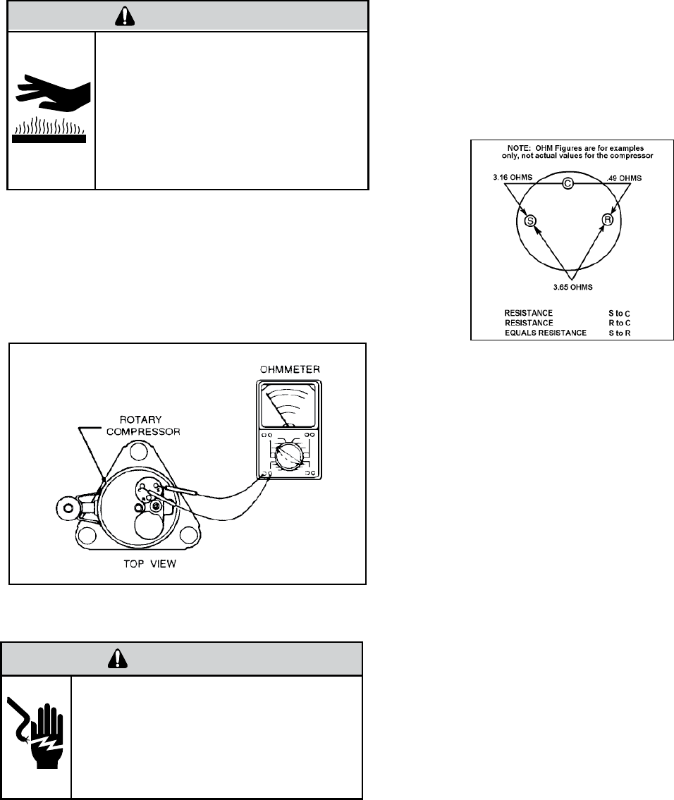
External Overload
With power off, remove the leads from compressor termi-
nals. If the compressor is hot, allow the overload to cool
before starting check. Using an ohmmeter, test continu-
ity across the terminals of the external overload. If you
do not have continuity; this indicates that the overload is
open and must be replaced.
Certain unit components operate at
temperatures hot enough to cause burns.
Proper safety procedures must be followed,
and proper protective clothing must be
worn.
Failure to follow this warning could result
in moderate to serious injury.
WARNING
BURN HAZARD
Single Phase Resistance Test
Remove the leads from the compressor terminals and set
the ohmmeter on the lowest scale (R x 1).
Touch the leads of the ohmmeter from terminals common
to start (“C” to “S”). Next, touch the leads of the ohmmeter
from terminals common to run (“C” to “R”).
Add values “C” to “S” and “C” to “R” together and
check resistance from start to run terminals (“S” to “R”).
Resistance “S” to “R” should equal the total of “C” to “S”
and “C” to “R.”
In a single phase PSC compressor motor, the highest
value will be from the start to the run connections (“S” to
“R”). The next highest resistance is from the start to the
common connections (“S” to “C”). The lowest resistance
is from the run to common. (“C” to “R”) Before replacing a
compressor, check to be sure it is defective.
ELECTRIC SHOCK HAZARD
WARNING
Turn off electric power before service or
installation. Extreme care must be used, if it
becomes necessary to work on equipment
with power applied.
Failure to do so could result in serious injury or
death.
Many compressor failures are caused by the following
conditions:
1. Improper air fl ow over the evaporator.
2. Overcharged refrigerant system causing liquid to be
returned to the compressor.
3. Restricted refrigerant system.
4. Lack of lubrication.
5. Liquid refrigerant returning to compressor causing oil
to be washed out of bearings.
6. Noncondensables such as air and moisture in
the system. Moisture is extremely destructive to a
refrigerant system.
GROUND TEST
Use an ohmmeter set on its highest scale. Touch one
lead to the compressor body (clean point of contact as a
good connection is a must) and the other probe in turn
to each compressor terminal. If a reading is obtained the
compressor is grounded and must be replaced.
Check the complete electrical system to the compressor
and compressor internal electrical system, check to be
certain that compressor is not out on internal overload.
Complete evaluation of the system must be made whenever
you suspect the compressor is defective. If the compressor
has been operating for sometime, a careful examination
must be made to determine why the compressor failed.
37
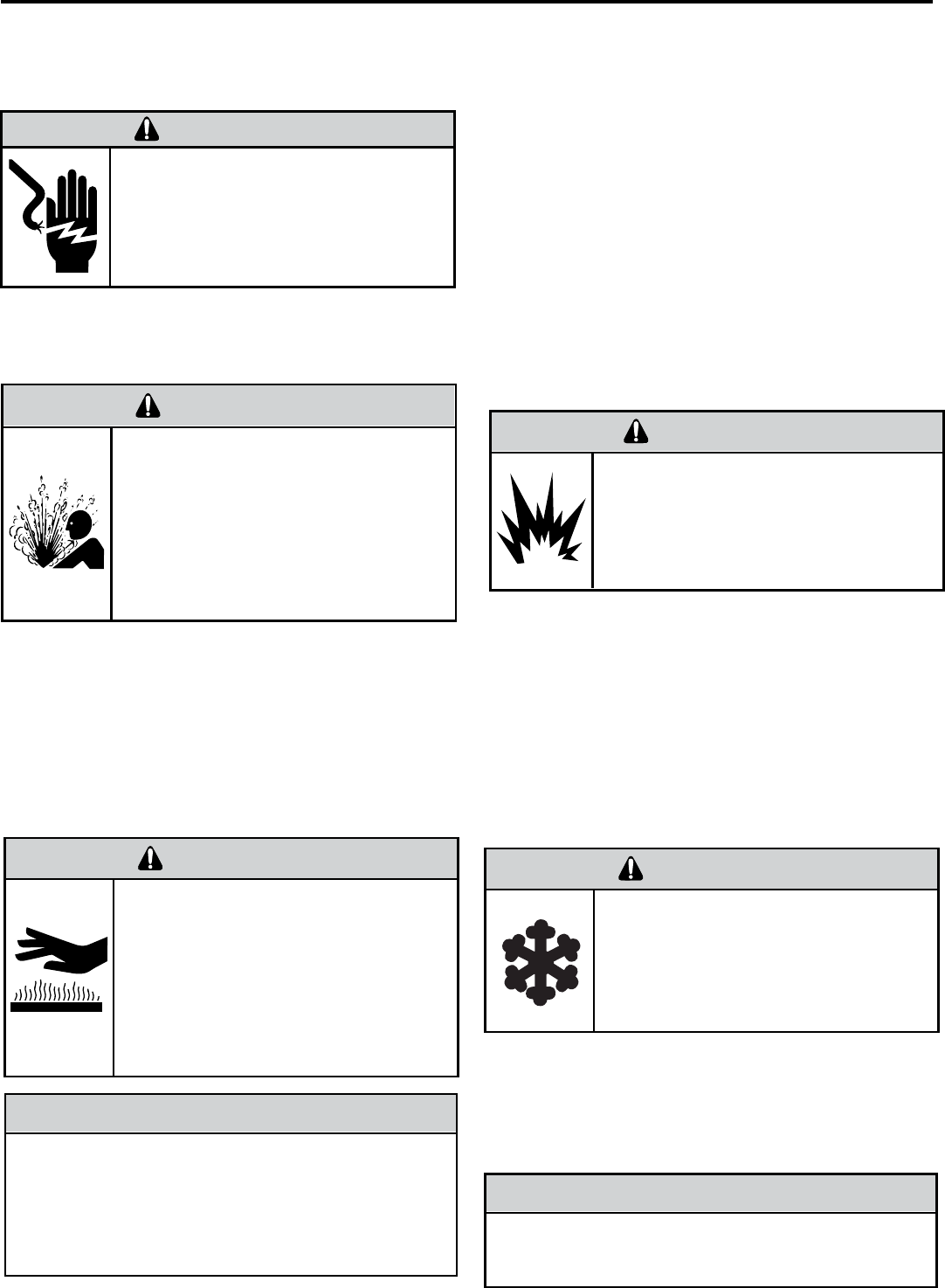
Recommended procedure for compressor
replacement
1. Be certain to perform all necessary electrical and
refrigeration tests to be sure the compressor is
actually defective before replacing.
2. Recover all refrigerant from the system though
the process tubes. PROPER HANDLING OF
RECOVERED REFRIGERANT ACCORDING TO
EPA REGULATIONS IS REQUIRED. Do not use
gauge manifold for this purpose if there has been
a burnout. You will contaminate your manifold and
hoses. Use a Schrader valve adapter and copper
tubing for burnout failures.
COMPRESSOR REPLACEMENT
Unplug and/or disconnect all electrical power
to the unit before performing inspections,
maintenances or service.
Failure to do so could result in electric shock,
serious injury or death.
WARNING
RISK OF ELECTRIC SHOCK
Sealed Refrigeration System contains refrigerant
and oil under high pressure.
Proper safety procedures must be followed,
and proper protective clothing must be worn
when working with refrigerants.
Failure to follow these procedures could
result in serious injury or death.
WARNING
HIGH PRESSURE HAZARD
Extreme care, proper judgment and all safety
procedures must be followed when testing,
troubleshooting, handling or working around
unit while in operation with high temperature
components. Wear protective safety aids
such as: gloves, clothing etc.
Failure to do so could result in serious burn
injury.
WARNING
HIGH TEMPERATURES
The use of a torch requires extreme care and proper
judgment. Follow all safety recommended precautions
and protect surrounding areas with fi re proof materials.
Have a fi re extinguisher readily available. Failure to follow
this notice could result in moderate to serious property
damage.
NOTICE
FIRE HAZARD
3. After all refrigerant has been recovered, disconnect
suction and discharge lines from the compressor and
remove compressor. Be certain to have both suction
and discharge process tubes open to atmosphere.
4. Carefully pour a small amount of oil from the suction
stub of the defective compressor into a clean
container.
9. Evacuate the system with a good vacuum pump capable
of a fi nal vacuum of 200 microns or less. The system
should be evacuated through both liquid line and suction
line gauge ports. While the unit is being evacuated, seal
all openings on the defective compressor.
10. Recharge the system with the correct amount of
refrigerant. The proper refrigerant charge will be
found on the unit rating plate. The use of an accurate
measuring device, such as a charging cylinder,
electronic scales or similar device is necessary.
5. Using an acid test kit (one shot or conventional kit), test
the oil for acid content according to the instructions
with the kit.
6. If any evidence of a burnout is found, no matter how
slight, the system will need to be cleaned up following
proper procedures.
7. Install the replacement compressor.
8. Pressurize with a combination of R-410A and nitrogen
Repeat Step 8 to insure no more leaks are present.
The use of nitrogen requires a pressure
regulator. Follow all safety procedures and
wear protective safety clothing etc.
Failure to follow proper safety procedures
result in serious injury or death.
WARNING
EXPLOSION HAZARD
Proper safety procedures must be followed,
and proper protective clothing must be worn
when working with liquid refrigerant.
Failure to follow these procedures could
result in minor to moderate injury.
CAUTION
FREEZE HAZARD
and leak test all connections with leak detector capable of
detecting HFC (Hydrofl uorocarbon) refrigerant. Recover
refrigerant/nitrogen mixture and repair any leaks found.
NEVER, under any circumstances, charge a rotary
compressor through the LOW side. Doing so would
cause permanent damage to the new compressor.
NOTICE
38
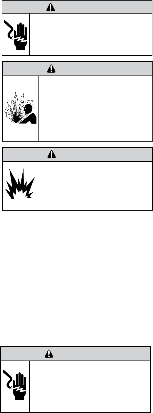
1.
2.
3.
4.
5.
ELECTRIC SHOCK HAZARD
WARNING
Turn off electric power before service or
installation.
Failure to do so may result in personal injury,
or death.
Sealed Refrigeration System contains refrigerant
and oil under high pressure.
Proper safety procedures must be followed,
and proper protective clothing must be worn
when working with refrigerants.
Failure to follow these procedures could
result in serious injury or death.
WARNING
HIGH PRESSURE HAZARD
The use of nitrogen requires a pressure
regulator. Follow all safety procedures and
wear protective safety clothing etc.
Failure to follow proper safety procedures
result in serious injury or death.
WARNING
EXPLOSION HAZARD
Recover all refrigerant and oil from the system.
Remove compressor, capillary tube and fi lter drier
from the system.
Flush evaporator condenser and all connecting
tubing with dry nitrogen or equivalent. Use approved
fl ushing agent to remove all contamination from
system. Inspect suction and discharge line for
carbon deposits. Remove and clean if necessary.
Ensure all acid is neutralized.
Reassemble the system, including new drier strainer
and capillary tube.
Proceed with step 8-10 on previous page.
SPECIAL PROCEDURE IN THE CASE OF MOTOR
COMPRESSOR BURNOUT
39
ROUTINE MAINTENANCE
ELECTRICAL SHOCK HAZARD!
WARNING
Turn off electrical power before service or
installation. All eletrical connections and wiring
MUST be installed by a qualifi ed electrician
and conform to the National Code and all local
codes which have jurisdiction. Failure to do so
can result in property damage, personal injury
and/or death.
To ensure proper unit operation and life expectancy, the
following maintenance procedures should be performed
on a regular basis
1. Air Filter
To ensure proper unit operation, the air fi lters should
be cleaned at least monthly, and more frequently if
conditions warrant. The unit must be turned off before
the fi lters are cleaned.
To remove the air fi lters, grasp the top of the fi lter and lift
out of the front cabinet. Reverse the procedure to reinstall
the fi lters.
Clean the fi lters with a mild detergent in warm water, and
allow them to dry thoroughly before reinstalling.
2. Coils & Chassis
NOTE: Do not use a caustic coil cleaning agent on coils
or base pan. Use a biodegradable cleaning agent and
degreaser. The use of harsh cleaning materials may
lead to deterioration of the aluminum fi ns or the coil end
plates.
The indoor coil and outdoor coils and base pan should
be inspected periodically (annually or semi-annually)
and cleaned of all debris (lint, dirt, leaves, paper, etc.)
as necessary. Under extreme conditions, more frequent
cleaning may be required. Clean the coils and base
pan with a soft brush and compressed air or vacuum.
A pressure washer may also be used, however, you
must be careful not to bend the aluminum fi n pack. Use
a sweeping up and down motion in the direction of the
vertical aluminum fi n pack when pressure cleaning coils.
Note: It is extremely important to insure that none of the
electrical and/or electronic parts of the unit get wet. Be
sure to cover all electrical components to protect them
from water or spray.
3. Decorative Front
The decorative front and discharge air grille may be
cleaned with a mild soap or detergent. Do NOT use
solvents or hydrocarbon based cleaners such as
acetone, naphtha, gasoline, benzene, etc., to clean the
decorative front or air discharge grilles.
Use a damp (not wet) cloth when cleaning the control
area to prevent water from entering the unit, and possibly
damaging the electronic control
4. Fan Motor & Compressor
The fan motor & compressor and are permanently
lubricated, and require no additional lubrication.
5. Wall Sleeve
Inspect the inside of the wall sleeve and drain system
periodically (annually or semi-annually) and clean as
required. Under extreme conditions, more frequent
cleaning may be necessary. Clean both of these areas
with an antibacterial and antifungal cleaner. Rinse both
items thoroughly with water and ensure that the drain
outlets are operating properly.
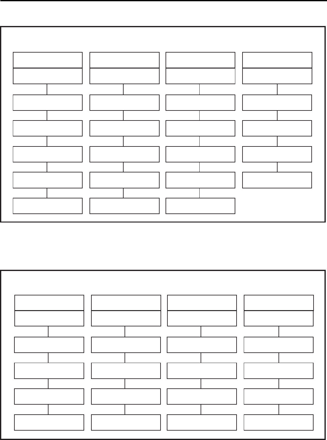
REFRIGERANT SYSTEM DIAGNOSIS COOLING
REFRIGERANT SYSTEM DIAGNOSIS HEATING
Low Load Conditions High Load Conditions Low Load Conditions High Load Conditions
Low Air Flow Across High Air Flow Across Refrigerant System Low Air Flow Across
Indoor Coil Indoor Coil Restriction Outdoor Coil
Refrigerant System Reversing Valve not Reversing Valve not
Overcharged
Restriction Fully Seated Fully Seated
Undercharged Overcharged
Non-Condensables (air)
Undercharged System
Moisture in System Defective Compressor Defective Compressor
LOW SUCTION PRESSURE HIGH SUCTION PRESSURE LOW HEAD PRESSURE HIGH HEAD PRESSURE
LOW SUCTION PRESSURE HIGH SUCTION PRESSURE LOW HEAD PRESSURE HIGH HEAD PRESSURE
PROBLEM PROBLEM PROBLEM PROBLEM
PROBLEM PROBLEM PROBLEM PROBLEM
Low Air Flow Across Outdoor Ambient Too High Refrigerant System Outdoor Ambient Too High
Outdoor Coil for Operation in Heating Restriction For Operation In Heating
Refrigerant System Reversing Valve not Reversing Valve not Low Air Flow Across
Restriction Fully Seated Fully Seated Indoor Coil
Undercharged Overcharged
Defective Compressor
Undercharged Overcharged
Moisture in System Defective Compressor
Non-Condensables (air)
in System
TROUBLESHOOTING CHART - COOLING
TROUBLESHOOTING CHART - HEATING
40
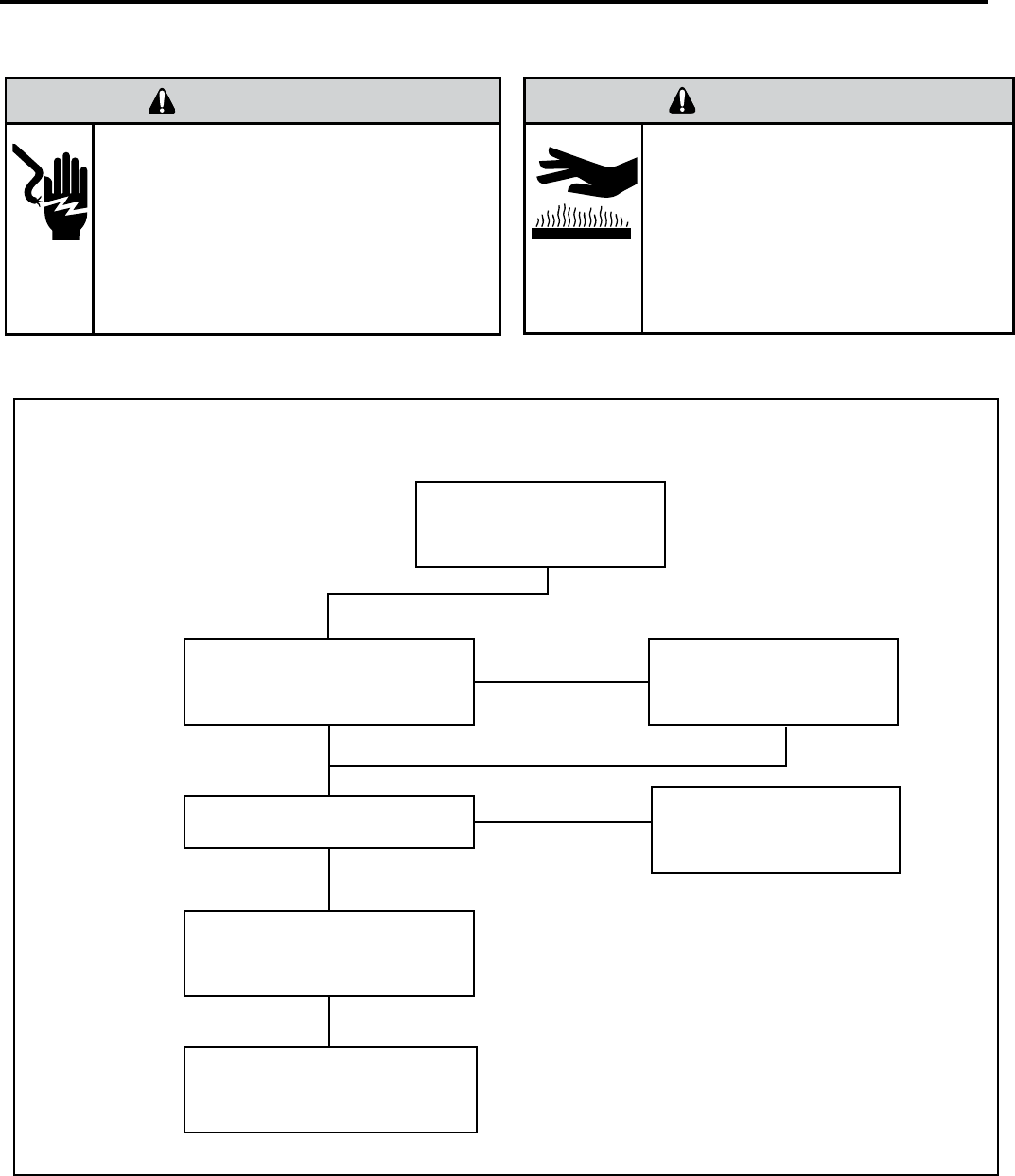
HEAT PUMP
SYSTEM COOLS WHEN
HEATING IS DESIRED.
Is Line Voltage
Present at the
Solenoid Valve?
Is the Selector Switch
Set for Heat?
NO
YES
Is the Solenoid Coil Good?
Replace the Solenoid Coil
NO
YES
Reversing Valve Stuck
Replace the Reversing Valve
ELECTRICAL TROUBLESHOOTING CHART - HEAT PUMP
ELECTRIC SHOCK HAZARD
WARNING
Turn off electric power before service or
installation.
Extreme care must be used, if it becomes
necessary to work on equipment with power
applied.
Failure to do so could result in serious injury
or death.
Certain unit components operate at
temperatures hot enough to cause burns.
Proper safety procedures must be followed,
and proper protective clothing must be
worn.
Failure to do so could result in minor to
moderate injury.
CAUTION
BURN HAZARD
41
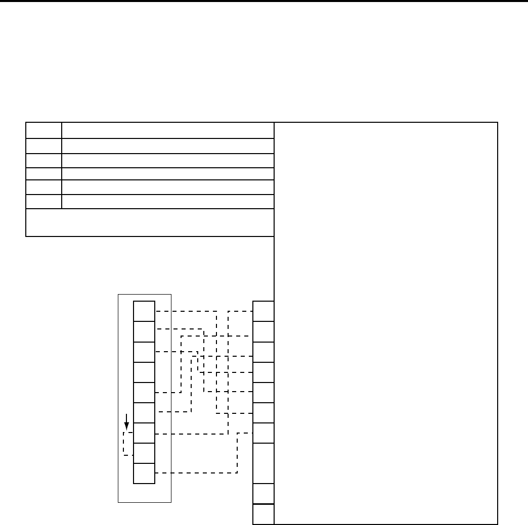
42
LEGEND FOR T-STAT WIRING HARNESS
R 24 VAC Power From Unit
Y Coil for Cooling
W Call for Heat
O Reversing Valve Energized in cooling mode
GL Call for Low Fan
GH Call for High Fan
RT6 - Two Speeds Fan T-Stat - Field Provided
-- -- -- Field Wiring
GH
GL
O
B
Y
W
RC
RH
C
R
W
O
GL
Y
GH
EXT.
SW
EXT.
SW
C
THERMOSTAT CONNECTIONS
Electronic
Control
Board
Jumper Wire
RT6
Disk control
or
Auxillary fan
REMOTE WALL THERMOSTAT WIRING DIAGRAM
COOL WITH ELECTRIC HEAT
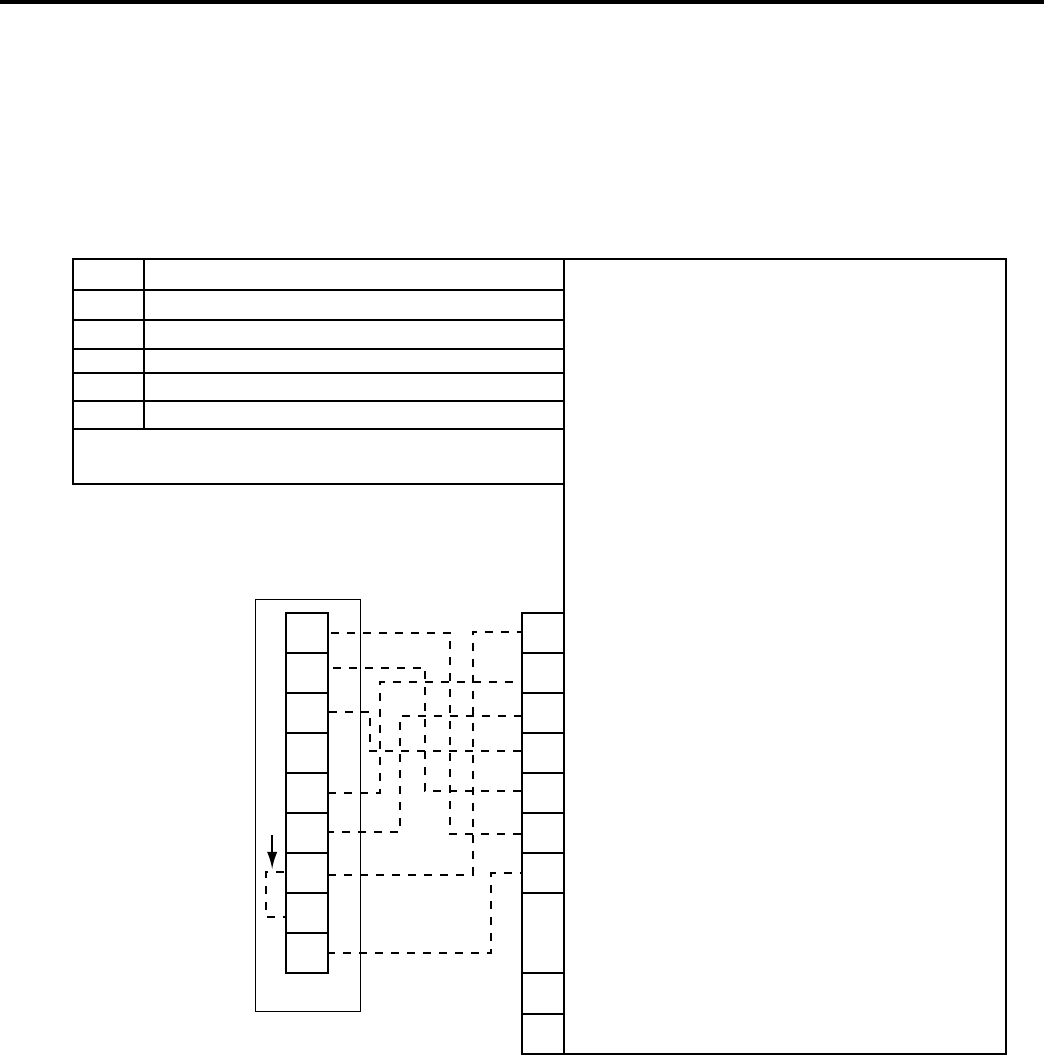
43
LEGEND FOR T-STAT WIRING HARNESS
R 24 VAC Power From Unit
Y Coil for Cooling
W Call for Heat
O Reversing Valve Energized in cooling mode
GL Call for Low Fan
GH Call for High Fan
RT6 - Two Speeds Fan T-Stat - Field Provided
-- -- -- Field Wiring
GH
GL
O
B
Y
W
RC
RH
C
R
W
O
GL
Y
GH
EXT.
SW
EXT.
SW
C
THERMOSTAT CONNECTIONS
Electronic
Control
Board
Jumper Wire
RT6
Disk control
or
Auxillary fan
REMOTE WALL THERMOSTAT WIRING DIAGRAM
HEAT PUMP WITH ELECTRIC HEAT
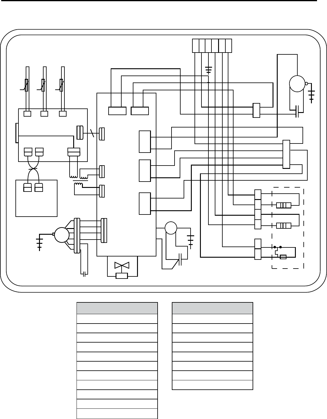
44
WIRING DIAGRAM
5VDC 5VDC
Thermistors
Indoor
Logic Board
Display
Control
Board
24VAC TB
X8
HR
BK
BN
RD
PR
4VN3
N4
WH
OFAN
Main Relay Board
PR
IM
YL
BL
WH
YV
Rev Solenoid
COMP = Compressor
COMPONENT ID
CAP = Capacitor
HTR = Heater
TB = Terminal Block
OM = Outdoor Fan Motor
IM = Indoor Fan Motor
TRAN = Transformer
RELAY COMM = L.V. Relay Cable
CR = Compressor Relay
HR = Heater Relay
YV = Reversing Valve Solenoid
BL = Blue
WIRE COLOR ID
BN = Brown
BK = Black
RD = Red
WH = White
PR = Purple
YL = Yellow
GR = Green
CAP
CAP
CAP
WH
BL
WH
WH
WH
BL
RD
BK
BK
L1TB
L2TB
BK
WH
L1
L2
GRD
L1
L1
L1
GR
RD
RD
BN
COMP
BK
BL
YL
BK
BK
BN
BNBK
BN
BK
BN
BN
BN
BL
RD
BL
HTR
HTR
Auto Reset
Limit
Fuse Link
RD
RD
OM
BN
RD
K103 K104
HR
CR HR HR
Air Outdoor
24VAC
12VAC
12VDC
RELAY COMM
Indoor Fan
X7X6X5
5VDC
12VDC
TRAN
208/230
265 VAC
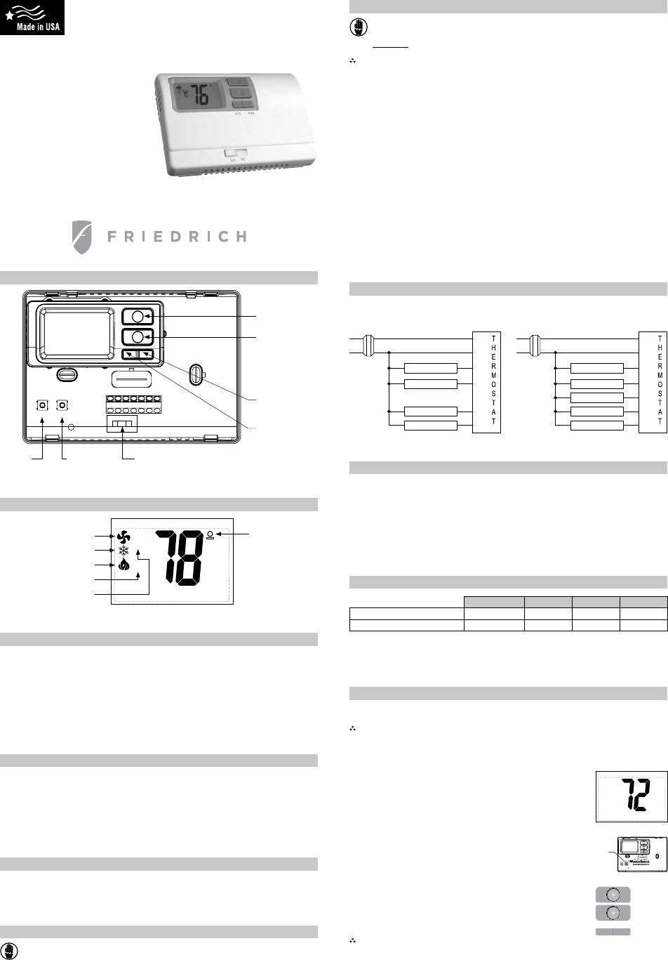
45
Icon Descriptions
Specifications
!"#$%&#'!(%'$&)*+ ! "# $%& '()*+, $%&-
! ( ./0 /.12/3/ 045 645/27.8
! + ./0 /.12/3/ 696.8 89.:
,"-."%'$/%"(#0)$%0!(%')*"+(#;<= 69 >,<= '?<& 69 +"<&- 1##/%'#2+ @ (<= '@ ,A;<&-
324$"-(#0)5*/%'$&0)4+ "*B6.C4 D4.6E (*B6.C4 F998E D4.6 03/0E 484F652F
,&-&)*+ %762*BD956 &GF84H # /27364B 'IG0.BB .762*BD956 FGF84 :48.G IG 54635727C 69 J== /9:4 K95 ; B4F97:B-
L.FM82CD6 J045.6297H (, B4F97:B
,"%-&)'$&0)4+ NE &E OPE OQE JRLE SE T
RT6
Electronic Thermostat
Installation, Operation & Application Guide
6(783$'*"(9"'$:783$'*"(;00!(324$"-4
6(;0)5*/%'<!"($0+(=84$'*"(>"'$(./-.
6(?'%*"(@&4.!'2(A&$>(B'#C!&*>$
6(3"!"#$'<!"(D'>%")>"&$(0%(;"!4&/4
Parts Diagram
&97UC35.6297
BV26FD
P9RQ2 K.7
BV26FD
N4B46
BV26FD
P4K6 'BGB64/-
I36697
N2CD6 'K.7-
I36697
W9V7 I36697
X0 I36697
SJRLOQOP&N T
NYZY[ &J\=]O
Package Contents/Tools Required
E'#C'*"(&)#!/F"4+ G,H 6D45/9B6.6 97 I.B4E 6D45/9B6.6 F9^45E V2527C 8.I48BE BF54VB .7: V.88 .7FD95BE ]7B6.88.6297E
J045.6297 .7: %0082F.6297 O32:4
,00!4(%"I/&%"F(J0%(&)4$'!!'$&0)+ W5288 V26D +R(_` I26E D.//45E BF54V:52^45
Important Safety Information
!"#$#%&
H
1!K'24($/%)(0JJ(.0K"%('$($>"(-'&)(.0K"%(4/..!2(<"J0%"(&)4$'!!&)*L(#!"')&)*L(0%(%"-0M&)*(
$>"%-04$'$N
! [D2B 6D45/9B6.6 2B K95 "# $%& .0082F.6297B 978Ga :9 796 3B4 97 ^986.C4B 9^45 +, $%&
! %88 V2527C /3B6 F97K95/ 69 89F.8 .7: 7.6297.8 484F652F.8 .7: I328:27C F9:4B
! W9 796 3B4 .25 F97:2629727C VD47 6D4 936:995 64/045.6354 2B I489V ;, :4C544Ba 6D2B F.7 :./.C4 G935 %R& BGB64/
.7: F.3B4 045B97.8 27b3524B
! XB4 6D2B 6D45/9B6.6 978G .B :4BF52I4: 27 6D2B /.73.8
To Remove Existing Thermostat
? ;,GO;1?(39P;Q(91R1G@
(S(,/%)(0JJ(.0K"%('$($>"(-'&)(4"%M&#"(.')"!(<2(%"-0M&)*($>"(J/4"(
0%(4K&$#>&)*($>"('..%0.%&'$"(#&%#/&$(<%"'C"%($0($>"(PDD(.04&$&0)(<"J0%"(%"-0M&)*($>"("T&4$&)*(
$>"%-04$'$N
(A [357 9KK 09V45 69 6D4 D4.627C .7: F99827C BGB64/ IG 54/9^27C 6D4 K3B4 95 BV26FD27C 6D4 .0059052.64 F25F326
I54.M45 9KKA
"A N4/9^4 F9^45 9K 98: 6D45/9B6.6A [D2B BD938: 4109B4 6D4 V254BA
+A P.I48 6D4 412B627C V254B V26D 6D4 47F89B4: V254 8.I48B I4K954 54/9^27C V254BA
#A %K645 8.I4827C V254BE 54/9^4 V254B K59/ V254 645/27.8BA
;A N4/9^4 412B627C 6D45/9B6.6 I.B4 K59/ V.88A
_A N4K45 69 6D4 K9889V27C B4F6297 K95 27B653F6297B 97 D9V 69 27B6.88 6D2B 6D45/9B6.6A
To Install Thermostat
? ;,GO;1?(39P;Q(91R1G@
(S(,/%)(0JJ(.0K"%('$($>"(-'&)(4"%M&#"(.')"!(<2(%"-0M&)*($>"(J/4"(
0%(4K&$#>&)*($>"('..%0.%&'$"(#&%#/&$(<%"'C"%($0($>"(PDD(.04&$&0)(<"J0%"(%"-0M&)*($>"("T&4$&)*(
$>"%-04$'$N
OUEPG,1V,+ !"#$%&'(')*+&'(,,('*%+)$-&').%+/%#$)'%),%.(,)(+0)+('*%+(,)1-*,0*+2)(+0)",".'#*.(,).%0"&)(+0)
%#0*+(+."&3)
V0$"+ 4%-+')'!")'!"#$%&'(')(1%-')56")/""')(1%6")'!")7%%#3)8%)+%')$%-+')'!")'!"#$%&'(')%+)(+)%-'&*0")9(,,:)*+)
0*#".')&-+,*2!':)1"!*+0)()0%%#:)%#)*+)(+)(#"()(//".'"0)1;)()6"+')%#)0-.'3
(A [357 9KK 09V45 69 6D4 D4.627C .7: F99827C BGB64/ IG 54/9^27C 6D4 K3B4 95 BV26FD27C 6D4 .0059052.64 F25F326
I54.M45 9KKA
"A [9 54/9^4 F9^45E 0388 C4768G .6 6D4 B4./ .6 6D4 690A
+A c36 6D45/9B6.6 I.B4 .C.27B6 6D4 V.88 VD454 G93 08.7 69 /9376 26 'L4 B354 V254B V288 K44: 6D593CD 6D4 V254
904727C 27 6D4 I.B4 9K 6D4 6D45/9B6.6-A
#A d.5M 6D4 08.F4/476 9K 6D4 /937627C D984BA
;A Z46 6D45/9B6.6 I.B4 .7: F9^45 .V.G K59/ V95M27C .54.A
_A XB27C . +R(_` :5288 I26E :5288 D984B 27 6D4 08.F4B G93 D.^4 /.5M4: K95 /937627CA
?A XB4 . D.//45 69 6.0 B300824: .7FD95B 27 /937627C D984BA
)A %82C7 6D45/9B6.6 I.B4 V26D /937627C D984B .7: K44: 6D4 F976598 V254B 6D593CD B826 27 6D45/.8 27653B297 I.55245 .7:
2769 V254 904727CA
>A XB4 B300824: BF54VB 69 /9376 6D45/9B6.6 I.B4 69 V.88A
(,A ]7B456 B652004:E 8.I484: V254B 27 /.6FD27C V254 645/27.8BA
;1W,OPVX+ <")&-#")"=>%&"0)>%#'*%+)%/)9*#"&)0%"&)+%')'%-.!)%'!"#)9*#"&3
((A O4768G 63C V254 69 I4 B354 9K 059045 F9774F6297A W93I84 FD4FM 6D.6 4.FD V254 2B F9774F64: 69 6D4 059045
645/27.8A
("A [357 97 09V45 69 6D4 BGB64/ .6 6D4 /.27 B45^2F4 0.748A
(+A &97UC354 6D45/9B6.6 69 /.6FD 6D4 6G04 9K BGB64/ G93 D.^4A
(#A N408.F4 F9^45 97 6D45/9B6.6 IG B7.0027C 26 27 08.F4A
(;A [4B6 6D45/9B6.6 9045.6297 .B :4BF52I4: 27 e[4B627C 6D4 [D45/9B6.6`A
Terminal Designator Descriptions
N f "# $%& D96
& f "# $%& F9//97
JRL f &97UC35.I84
J f &998 .F62^4 54^45B27C ^.8^4 '=542:52FD c[Qc-
L f Q4.6 .F62^4 54^45B27C ^.8^4 '=542:52FD $456*]*c.ME g3D8hQc-
S f (B6 B6.C4 F998E (B6 B6.C4 D4.6 K95 D4.6 03/0B
T f (B6 B6.C4 D4.6 K95 797*D4.6 03/0 BGB64/BE .31282.5G D4.6 K95 Qc BGB64/B
OP f P9V K.7
OQ f Q2CD K.7
RT6 Output Chart
Wiring Diagrams
9"'$:;00!(324$"-4 9"'$(./-.(K&$>("!"#$%&#(<'#C/.
(",
$%&
"# $%&
P9V =.7
Q2CD =.7
&9/054BB95
N4^45B27C $.8^4
%31282.5G Q4.6
[5.7BK95/45
&
OP
OQ
JRL
S
T
N
(",
$%&
"# $%&
P9V =.7
Q2CD =.7
&998
Q4.6
[5.7BK95/45
&
OP
OQ
JRL
S
T
N
=.7 9045.6297 2F97
&99827C 9045.6297 2F97
Q4.627C 9045.6297 2F97
Q4.6 B46 09276 VD47 I827M27C
&998 B46 09276 VD47 I827M27C
N99/ 64/045.6354
9KKB46 .F62^.64:
&JJP
QY%[
Configuration
1
ST
Cool 1
ST
Heat 2
ND
Heat
Q4.6R&998 .7: B27C84 B6.C4 Qc /9:48B YP& SE O TE OE L \R%
cWQ 'c[Qc- /9:48B 978G Qc iJj &97UC SE OE J SE O SE TE O
[D4 G,H 6D45/9B6.6 2B F97UC35.I84 K95 :2KK45476 BGB64/BA [D4 F97UC35.6297 :254F68G .KK4F6B 6D4 936036BA
XB4 6D4 936036 FD.56 69 F9554F68G F97UC354 .7: V254 6D4 6D45/9B6.6 69 G935 BGB64/A
!!
(A $452KG 6D4 G,H 2B 27 6D4 PDD /9:4A
c54BB 6D4 3Y3 '84K6- I36697 37628 9KK /9:4 :2B08.GBA
"A N4/9^4 6D4 F9^45 9K 6D4 6D45/9B6.6 IG C4768G 038827C 74.5 974 9K 6D4 F95745B .6
6D4 690 9K 6D4 6D45/9B6.6A
Configuration Mode
c54BB 6D4 /. 95 F0K) I36697 69 FD.7C4 B46627CB V26D27 4.FD BF5447A
[9 4126 F97UC35.6297 /9:4E 054BB 6D4 ;PVDOZ BV26FD K95 ( B4F97:A
c54BB 6D4 %&*>$ I36697 69 .:^.7F4 69 6D4 7416 BF5447A
V0$"+ ?#"&&*+2)'!")
"#$%
)1-''%+)9*,,)#"'-#+);%-)'%)'!")>#"6*%-&)&.#""+3
W9V7
I36697
X0
I36697
P4K6
I36697
N2CD6
I36697
[D4 F97UC35.6297 /9:4 2B 3B4: 69 B46 6D4 G,H 69 /.6FD G935 D4.627CRF99827C BGB64/A [D4 G,H K37F6297B V26D D4.6
03/0E .25 F97:2629727CE 95 484F652F D4.6 BGB64/BA
V0$"+
!"#$%&'(').%$"&).%+52-#"0)/%#)@A&'(2")!"(')B)@A&'(2").%%,*+2)/%#)-&")9*'!)(,,)!"('B.%%,)(+0)&*+2,"A&'(2")!"(')
>-$>)$%0",&3C%#)C#*"0#*.!)? D?)$%0",&)/%,,%9)'!")*+&'#-.'*%+&)1",%9)'%).%+52-#")'!")'!"#$%&'(')/%#)'9%A&'(2")
!"(')>-$>)%>"#('*%+)-&*+2)'!")EFG)'"#$*+(,3
[9 F97UC354 6D4 G,HE 045K95/ 6D4 K9889V27C B640BH
+A c54BB 6D4 ;PVDOZ I36697 K95 ( B4F97: VD284 6D4 G,H 2B 27 PDD(/9:4A
&J\=]O
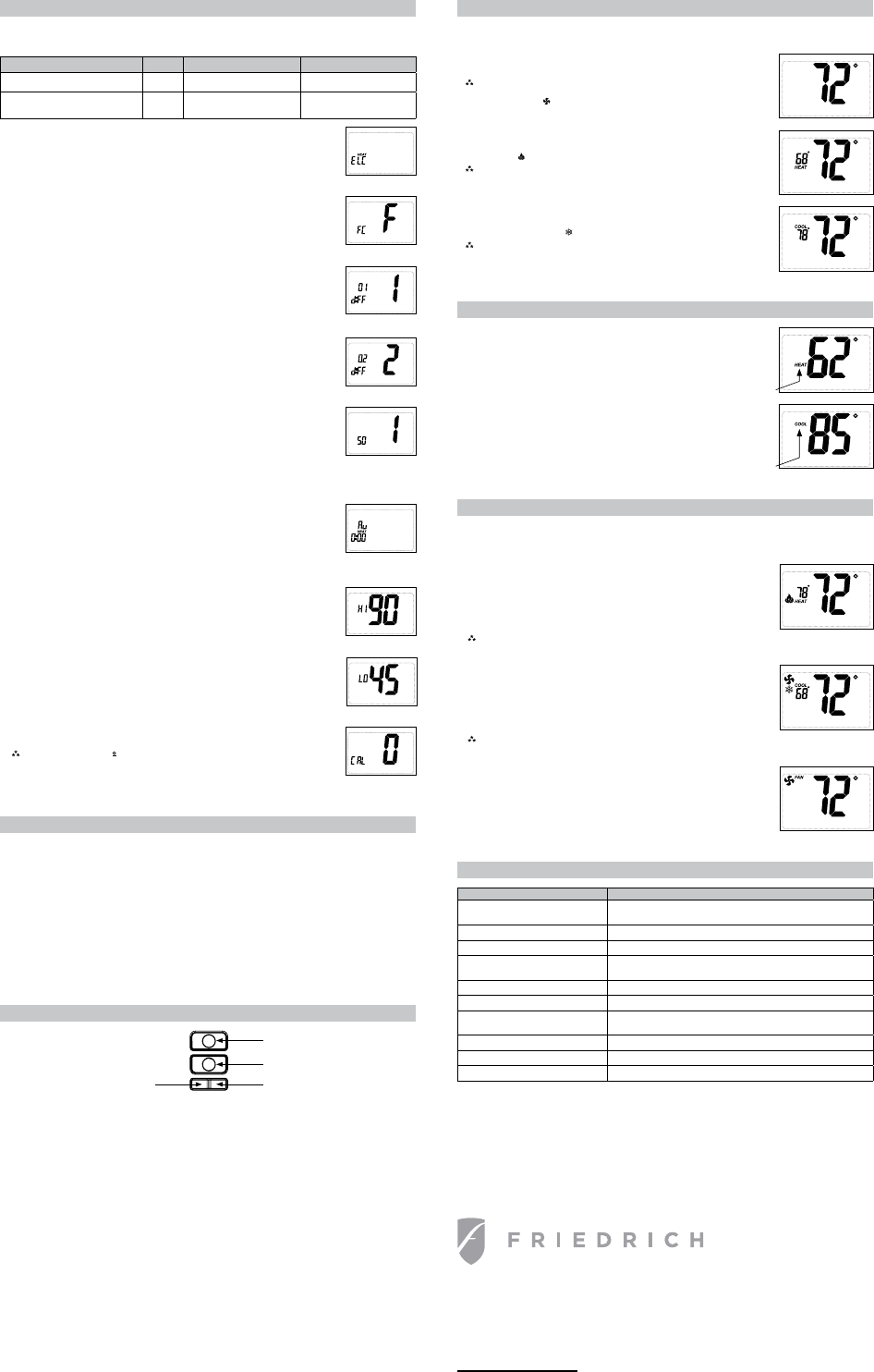
Configuration Mode Settings
!"#$"%&'#$()""*$#+,)#-,*./&)0%1,*#2,3"#0)"#0$#+,44,5$6
78# !"#$%&'((&')!*)!+# !"#$%&$'$"()*+##
# 9"4"(%#5!"%!")#%!"#,&%'&%$#+,)#!"0%1*/#0*3#(,,41*/#0)"#$%0/"3#,++#1*3"'"*3"*%4:#,)#0)"#
$0%1$."3#$1;&4%0*",&$4:8
# <#=#,&%'&%$#$%0/"3#,++#1*3"'"*3"*%4:#####
# >#=#,&%'&%$#,++#$1;&4%0*",&$4:
# ?)"$$#%!"#)*#,)#%,-.#@&%%,*#%,#$"%8
# ?)"$$#%!"#/0#1!&@&%%,*#%,#03A0*("#%,#%!"#*"B%#$()""*8
C8# 2
.%
& !"#$&3$4*$/"!)/$&50(($/$.!0"6#D<EF#%,#7EFG#D>87E-#%,#H87E-G# !"#$%&$'$"()*+
# 9"%#%!"#*&;@")#,+#3"/)""$#@"%5""*#5!"*#$%0/"#<#%&)*$#,*#0*3#5!"*#$%0/"#H#%&)*$#,*8
# ?)"$$#%!"#)*#,)#%,-.#@&%%,*#%,#$"%#31++")"*%104#A04&"8
# ?)"$$#%!"#/0#1!&@&%%,*#%,#03A0*("#%,#%!"#*"B%#$()""*8
I8# 7
+!
& !"#$&3$4*$/"!)/$&50(($/$.!0"6#D<EF#%,#7EFG#D>87E-#%,#H87E-G
9"%#%!"#*&;@")#,+#3"/)""$#@"%5""*#:,&)#J$"%',1*%K#%";'")0%&)"#0*3#:,&)#J%&)*#,*K#
%";'")0%&)"8
# ?)"$$#%!"#)*#,)#%,-.#@&%%,*#%,#$"%#31++")"*%104#A04&"8
# ?)"$$#%!"#/0#1!&@&%%,*#%,#03A0*("#%,#%!"#*"B%#$()""*8
H8# 3$4*$/"!)/$& 8"6$&DF#,)#-G
& -!,,$"#F0!)"*!"1%#,)#-"4$1&$8
# ?)"$$#%!"#)*#,)#%,-.#@&%%,*#%,#$"4"(%8
# ?)"$$#%!"#
/0#1!
#@&%%,*#%,#03A0*("#%,#%!"#*"B%#$()""*8
<8# 9+!$4#L#9"%#+,)#!"0%#'&;'M#*,*N!"0%#'&;'M#)"A")$1*/#A04A"#,'")0%1,*
Operating Modes
!")"#0)"#+,&)#',$$1@4"#,'")0%1*/#;,3"$#+,)#%!"#:3;8#O++M#P"0%M#0*3#-,,4#;,3"$#0)"#0(("$$"3#@:#')"$$1*/#%!"# < #
D4"+%G#@&%%,*8
OFF Mode
Q# R*#%!1$#;,3"M#%!"#%!");,$%0%#5144#*,%#%&)*#,*#%!"#!"0%1*/#,)#(,,41*/#3"A1("$
#=,!$># !"#$%&''(#)*%#+*%#,"#-.(%"&#'%#/*%.*001#$%#"2"(1#'3"(*-$%4#/'&"#,1#
3("55$%4#-!"#!,-#6($4!-7#,.--'%8# !"#9'(&#!,-$5!'95#'%#-!"#&$530*1#*%&#
-!"#)*%#$+'%#
#*33"*(5#9!"%#-!"#)*%#'3"(*-"58
.!!
Heat Mode
Q# R*#%!1$#;,3"M#%!"#%!");,$%0%#(,*%),4$#%!"#!"0%1*/#$:$%";8#S!"*#%!"#!"0%#,&%'&%$M#
%!"#T0;"#1(,*#
#0'')"0)$#,*#%!"#31$'40:8
#=,!$>#:'(#!"*-#3./35;#-!"("#$5#*#)'.(#/$%.-"#&"0*1#)'(#1'.(#+'/3("55'(#-'#
("5-*(-#*)-"(#$-#!*5#-.(%"&#'))8# '#,13*55#-!"#+'/3("55'(#-$/"#&"0*1;#4'#-'#
<::#/'&"#)'(#=#5"+'%&58
Cool Mode
Q# R*#%!1$#;,3"M#%!"#%!");,$%0%#(,*%),4$#%!"#(,,41*/#$:$%";8#S!"*#%!"#(,,41*/#
,&%'&%$M#%!"#$*,5T0U"#1(,*#
#0'')"0)$#,*#%!"#31$'40:8
#=,!$># !"("#$5#*#)'.(#/$%.-"#&"0*1#)'(#1'.(#+'/3("55'(#-'#("5-*(-#*)-"(#$-#!*5#
-.(%"&#'))8# '#,13*55#-!"#+'/3("55'(#-$/"#&"0*1;#4'#-'#<::#/'&"#)'(#=#
5"+'%&58
VRWF<HX
F)1"3)1(!#W1)#-,*31%1,*1*/#-,8
?,$%#O+.("#Y,B#<7C>#Q#90*#W*%,*1,M# "B0$#Z[H\7N<7C>
CH>>#]8#?0*#W;#^B')"$$50:#Q#90*#W*%,*1,M# "B0$#Z[H<[N7H<H
DH<>G#I7ZNCC>>#Q#FW_#DH<>G#I7ZNCC[>
5558+)1"3)1(!8(,;
;?& @)A060"/9&5$6"9&'=#L#D>NI>#;1*&%"$G# !"#$%&$'$"()*+
# 9"%#%!"#3"40:#%1;"#1*#;1*&%"$#+,)#0&B1410):#!"0%#%,#@"#4,(U"3#,&%#0+%")#0#(044#+,)#$"(,*3#
$%0/"8# !1$#"B%)0#$0A1*/$#+"0%&)"#1$#&$"3#%,#%";',)0)14:#4,(U#,&%#0&B1410):#!"0%#3"A1("$M#
044,51*/#`&$%#!"0%#'&;'#%,#%):#%,#$0%1$+:#!"0%#(0448
# ?)"$$#%!"#)*#,)#%,-.#@&%%,*#%,#$"4"(%8
& ?)"$$&%!"#/0#1!&@&%%,*#%,#03A0*("#%,#%!"#*"B%#$()""*8
Mode of Operation
!"#:3;#1$#0#<N$%0/"#,)#HN$%0/"#!"0%#%!");,$%0%8#R%#+&*(%1,*$#51%!#01)#(,*31%1,*1*/M#!"0%#'&;'$M#,)#"4"(%)1(#!"0%#
$:$%";$8#
!"#%!");,$%0%#0(%1A0%"$#%!"#!"0%1*/#0''410*("#5!"*#%!"#),,;#%";'")0%&)"#1$#@"4,5#%!"#$"%#!"0%#%";'")0%&)"#
D@:#%!"#31++")"*%104#%";'")0%&)"G8# !"#:3;#5144#$%,'#,&%'&%%1*/#5!"*#%!"#(044#+,)#!"0%#!0$#@""*#$0%1$."38#S1%!#
!"0%#'&;'$M#%!"#%!");,$%0%#5144#*,%#4"%#%!"#(,;')"$$,)#(,;"#,*#+,)#C#;1*&%"$#0+%")#1%#%&)*$#,++8# !1$#'),%"(%$#:,&)#
(,;')"$$,)8
S!"*#%!"#),,;#%";'")0%&)"#1$#/)"0%")#%!0*#%!"#$"%#(,,4#%";'")0%&)"#D@:#%!"#31++")"*%104#%";'")0%&)"GM#%!"#(,,41*/#
3"A1("#1$#0(%1A0%"38# !"#:3;#5144#$%,'#,&%'&%%1*/#5!"*#%!"#(044#+,)#(,,41*/#1$#$0%1$."38# !"#%!");,$%0%#5144#*,%#4"%#%!"#
(,;')"$$,)#(,;"#,*#+,)#C#;1*&%"$#0+%")#1%#%&)*$#,++8# !1$#'),%"(%$#:,&)#(,;')"$$,)8
!"#:3;#!0$#%!)""#',$$1@4"#,'")0%1*/#;,3"$6#'BBM#C$"!M#0*3#D,,6&;,3"8#R*#,++#;,3"M#%!"#%!");,$%0%#5144#*,%#%&)*#
,*#!"0%1*/#,)#(,,41*/#3"A1("$8# !"#;0*&04#+0*#(0*#@"#%&)*"3#,*#1*#044#,'")0%1*/#;,3"$#&$1*/#%!"#+0*#@&%%,*8#R*#!"0%#
;,3"M#%!"#%!");,$%0%#(,*%),4$#%!"#!"0%1*/#$:$%";8#R*#%!"#(,,4#;,3"M#%!"#%!");,$%0%#(,*%),4$#%!"#(,,41*/#$:$%";8#
Z8# E"A04)4&C$"!& $!*,0.!#DC7EF#%,#\>EFG#DZE-#%,#IHE-G#
# W3`&$%#%,#(,*%),4#%!"#;0B1;&;#!"0%#$"%#%";'")0%&)"#044,5"38
# ?)"$$#%!"#)*#,)#%,-.#@&%%,*#%,#$"4"(%8
# ?)"$$#%!"#/0#1!#@&%%,*#%,#03A0*("#%,#%!"#*"B%#$()""*8
[8# E0.04)4&D,,6& $!*,0.!#DC7EF#%,#\>EFG#DZE-#%,#IHE-G#
# W3`&$%#%,#(,*%),4#%!"#;1*1;&;#(,,4#$"%#%";'")0%&)"#044,5"38
# ?)"$$#%!"#)*#,)#%,-.#@&%%,*#%,#$"4"(%8
# ?)"$$#%!"#/0#1!#@&%%,*#%,#03A0*("#%,#%!"#*"B%#$()""*8
\8# :,,4&3$4*$/"!)/$&'((+$!#Da\EF#%,#N\EFG#DaC87E-#%,#NC87E-G#
# W3`&$%#%,#(041@)0%"#31$'40:"3#),,;#%";'")0%&)"#%,#;0%(!#0(%&04#),,;#%";'")0%&)"8#
#
#=,!$>#>!"%#%'-#5"-#-'#?;# $9$00#&$530*18
# ?)"$$#%!"#)*#,)#%,-.#@&%%,*#%,#$"4"(%8
# ?)"$$#%!"#/0#1!#@&%%,*#%,#03A0*("#%,#%!"#*"B%#$()""*8
Button Functions
FG#L#b$"3#%,#1*()"0$"#%!"#$"%#%";'")0%&)"$#0*3#%,#03`&$%#(,*./&)0%1,*#$"%%1*/$8#
5'H=#L#b$"3#%,#3"()"0$"#%!"#$"%#%";'")0%&)"$#0*3#%,#03`&$%#(,*./&)0%1,*#$"%%1*/$8
< &I6$(!J#L#b$"3#%,#(!0*/"#+),;#OFFM#P^W M#0*3#-OOV#;,3"$
B@=&I/0#1!J#L#b$"3#%,#%&)*#,*#0*3#,++#%!"#1*3,,)#+0*8
< %";#D4"+%G
B@=#D)1/!%G
5,-.#@&%%,*
F*#@&%%,*
Heat Set Point
Q# b$"#%!"#9c9#@&%%,*#%,#$"4"(%#P"0%#2,3"8#?)"$$#%!"#&'#,)#3,5*#@&%%,*#%,#A1"5#%!"#
(&))"*%#!"0%#$"%#',1*%#40)/")#,*#%!"#31$'40:8#S!"*#%!"#40)/"#$"%#',1*%#1$#31$'40:"3M#
%!"#P^W #1(,*#5144#@41*U8# !"#&'#,)#3,5*#@&%%,*$#(0*#@"#&$"3#%,#03`&$%#%!"#$"%#
',1*%8#W+%")#7#$"(,*3$#,+#1*0(%1A1%:#%!"#$()""*#5144#31$'40:#%!"#),,;#%";'")0%&)"#0*3#
%!"#P^W #1(,*#5144#*,%#@41*U8
%/,0$12"($31))$4)1(56
Cool Set Point
Q# b$"#%!"#9c9#@&%%,*#%,#$"4"(%#-,,4#2,3"8#?)"$$#%!"#&'#,)#3,5*#@&%%,*#%,#A1"5#%!"#
(&))"*%#(,,4#$"%#',1*%#40)/")#,*#%!"#31$'40:8#S!"*#%!"#40)/"#$"%#',1*%#1$#31$'40:"3M#
%!"#-OOV#1(,*#5144#@41*U8# !"#&'#,)#3,5*#@&%%,*$#(0*#@"#&$"3#%,#03`&$%#%!"#$"%#
',1*%8#W+%")#7#$"(,*3$#,+#1*0(%1A1%:#%!"#$()""*#5144#31$'40:#%!"#),,;#%";'")0%&)"#0*3#
%!"#-OOV#1(,*#5144#*,%#@41*U8
7..8$12"($31))$4)1(56
Set Point Adjustment
Troubleshooting
Symptom Remedy
],#31$'40: -!"(U#+,)#HC#dW-#0%#%!");,$%0%e#31$'40:#1$#@40*U#5!"*#HC#dW-#1$#*,%#
')"$"*%
W44#%!");,$%0%#@&%%,*$#0)"#1*,'")0%1A" d")1+:#HC#dW-#1$#')"$"*%e#&*1%#4,(U$#,&%#5!"*#HC#dW-#1$#*,%#')"$"*%
],#)"$',*$"#51%!#.)$%#@&%%,*#')"$$ F1)$%#@&%%,*#')"$$#0(%1A0%"$#@0(U41/!%#,*4:
!");,$%0%#%&)*$#,*#0*3#,++#%,,#
+)"f&"*%4:
W3`&$%#%";'")0%&)"#31++")"*%104##
D$""#-,*./&)0%1,*#2,3"#9"%%1*/$#I#g#CG
F0*#)&*$#(,*%1*&,&$4: ?)"$$#FW]#D)1/!%G#@&%%,*#%,#%&)*#+0*#,++
h,,;#%";'")0%&)"#1$#*,%#(,))"(% -041@)0%"#%!");,$%0%#D$""#-,*./&)0%1,*#2,3"#9"%%1*/#<>G
P"0%#,)#-,,4#*,%#(,;1*/#,* d")1+:#51)1*/#1$#(,))"(%M#/"*%4:#'&44#,*#"0(!#51)"#%,#A")1+:#%!")"#1$#0#/,,3#
(,**"(%1,*#0%#%");1*04#@4,(U
P^W #@41*U1*/ R*#!"0%#$"%#',1*%#$()""*
-OOV#@41*U1*/ R*#(,,4#$"%#',1*%#$()""*
?),@4";#*,%#41$%"3#0@,A" ?)"$$#h"$"%#@&%%,*#,*("i
K&:$+$!&L)!!,.&B).8!0,.6#
@$530*1#$5#(")("5!"&;#+'%A4.(*-$'%#5"--$%45#*("#.%+!*%4"&8
Testing the Thermostat
O*("#%!"#%!");,$%0%#1$#(,*./&)"3M#1%#$!,&43#@"#%!,),&/!4:#%"$%"38
!"#$%&'(
6#
j,#*,%#"*")/1k"#%!"#01)#(,*31%1,*1*/#$:$%";#5!"*#%!"#,&%3,,)#%";'")0%&)"#1$#@"4,5#7>#
3"/)""$8#R%#(0*#)"$&4%#1*#"f&1';"*%#30;0/"#,)#'")$,*04#1*`&):8
Heat Test
<8#?)"$$# < #D4"+%G#@&%%,*#&*%14#!"0%#;,3"#1$#31$'40:"38
H8#W3`&$%#%!"#$"%#%";'")0%&)"#$,#1%#1$#7#3"/)""$#0@,A"#%!"#),,;#%";'")0%&)"8
I8#P"0%#$!,&43#(,;"#,*#51%!1*#0#+"5#$"(,*3$8#
C8#W3`&$%#%!"#$"%#%";'")0%&)"#H#3"/)""$#@"4,5#%!"#),,;#%";'")0%&)"#0*3#%!"#!"0%#
$!,&43#%&)*#,++8# !")"#;0:#@"#0#+0*#3"40:#,*#:,&)#$:$%";8
#=,!$>#
F,)#!"0%#'&;'$M#%!")"#1$#0#+,&)N;1*&%"#3"40:#%,#'),%"(%#:,&)#(,;')"$$,)#0+%")#1%#%&)*$#,++8# ,#@:'0$$#%!"#
(,;')"$$,)#%1;"#3"40:M#/,#%,#OFF#;,3"#+,)#7#$"(,*3$8
Fan Test
<8# ?)"$$#B@=#D)1/!%G#@&%%,*8#F0*#31$'40:$8#R*3,,)#+0*#%&)*$#O]8
H8# ?)"$$#B@=#D)1/!%G#@&%%,*8#R*3,,)#+0*#%&)*$#OFF8
.!!
Cool Test
<8# ?)"$$# < #D4"+%G#@&%%,*#&*%14#(,,4#;,3"#1$#31$'40:"38#
H8# W3`&$%#$"%#%";'")0%&)"#$,#1%#1$#7#3"/)""$#@"4,5#),,;#%";'")0%&)"8
I8# Wl-#$!,&43#(,;"#,*#51%!1*#0#+"5#$"(,*3$8#
C8# W3`&$%#%!"#$"%#%";'")0%&)"#H#3"/)""$#0@,A"#%!"#),,;#%";'")0%&)"#0*3#%!"#Wl-##
$!,&43#%&)*#,++8# !")"#;0:#@"#0#+0*#3"40:#,*#:,&)#$:$%";8
#
#=,!$>#
!")"#1$#0#+,&)N;1*&%"#%1;"#3"40:#%,#'),%"(%#%!"#(,;')"$$,)#0+%")#1%#8# ,#@:'0$$#%!"#(,;')"$$,)#%1;"#
3"40:M#/,#%,#OFF#;,3"#+,)#7#$"(,*3$8
# ?)"$$#%!"#)*#,)#%,-.#@&%%,*#%,#$"4"(%8
# ?)"$$#%!"#/0#1!#@&%%,*#%,#03A0*("#%,#%!"#*"B%#$()""*8
9+!$4 $!!0.# :$M$/+0.#&N"6M$& $!!0.# B/0$%/081&E,%$6+
C$"!&G)4* P? O#N#^*")/1k"3#1*#-,,41*/
?jP#D? P?G O*4:
C$"!OD,,6&".%& 0.#6$P !"#$&
C$"!&G)4*&'.69
^V- ]lW d^WM#?j^#D? W-GM#m&!4a
46

47
Resistance Table for Air Indoor Temperature Sensor
Temp.
F!
Resistance
kȍ!
"
Temp.
F!
Resistance
kȍ!
"
Temp.
F!
Resistance
kȍ!
"
Temp.
F!
Resistance
kȍ!
-19 138.100
"
20 18.750
"
59 3.848
"
98 1.071
-18 128.600
"
21 17.930
"
60 3.711
"
99 1.039
-17 121.600
"
22 17.140
"
61 3.579
"
100 1.009
-16 115.000
"
23 16.390
"
62 3.454
"
101 0.980
-15 108.700
"
24 15.680
"
63 3.333
"
102 0.952
-14 102.900
"
25 15.000
"
64 3.217
"
103 0.925
-13 97.400
"
26 14.360
"
65 3.105
"
104 0.898
-12 92.220
"
27 13.740
"
66 2.998
"
105 0.873
-11 87.350
"
28 13.160
"
67 2.896
"
106 0.848
-10 82.750
"
29 12.600
"
68 2.797
"
107 0.825
-9 78.430
"
30 12.070
"
69 2.702
"
108 0.802
-8 74.350
"
31 11.570
"
70 2.611
"
109 0.779
-7 70.500
"
32 11.090
"
71 2.523
"
110 0.758
-6 66.880
"
33 10.630
"
72 2.439
"
111 0.737
-5 63.460
"
34 10.200
"
73 2.358
"
112 0.717
-4 60.230
"
35 9.779
"
74 2.280
"
113 0.697
-3 57.180
"
36 9.382
"
75 2.206
"
114 0.678
-2 54.310
"
37 9.003
"
76 2.133
"
115 0.660
-1 51.590
"
38 8.642
"
77 2.064
"
116 0.642
0 49.020
"
39 8.297
"
78 1.997
"
117 0.625
1 46.600
"
40 7.967
"
79 1.933
"
118 0.608
2 44.310
"
41 7.653
"
80 1.871
"
119 0.592
3 42.140
"
42 7.352
"
81 1.811
"
120 0.577
4 40.090
"
43 7.065
"
82 1.754
"
121 0.561
5 38.150
"
44 6.791
"
83 1.699
"
122 0.547
6 36.320
"
45 6.529
"
84 1.645
"
123 0.532
7 34.580
"
46 6.278
"
85 1.594
"
124 0.519
8 32.940
"
47 6.038
"
86 1.544
"
125 0.505
9 31.380
"
48 5.809
"
87 1.497
"
126 0.492
10 29.900
"
49 5.589
"
88 1.451
"
127 0.480
11 28.510
"
50 5.379
"
89 1.408
"
128 0.467
12 27.180
"
51 5.197
"
90 1.363
"
129 0.456
13 25.920
"
52 4.986
"
91 1.322
"
130 0.444
14 24.730
"
53 4.802
"
92 1.282
"
131 0.433
15 23.600
"
54 4.625
"
93 1.244
"
132 0.422
16 22.530
"
55 4.456
"
94 1.207
"
133 0.412
17 21.510
"
56 4.294
"
95 1.171
"
134 0.401
18 20.540
"
57 4.139
"
96 1.136
"
135 0.391
19 19.630
"
58 3.990
"
97 1.103
"
136 0.382

48
Resistance Table for Frost Protection Indoor and Outdoor Temperature Sensors
Temp.
F!
Resistance
kȍ!
"
Temp.
F!
Resistance
kȍ!
"
Temp.
F!
Resistance
kȍ!
"
Temp.
F!
Resistance
kȍ!
-19 181.400
"
20 25.010
"
59 5.130
"
98 1.427
-18 171.400
"
21 23.900
"
60 4.948
"
99 1.386
-17 162.100
"
22 22.850
"
61 4.773
"
100 1.346
-16 153.300
"
23 21.850
"
62 4.605
"
101 1.307
-15 145.000
"
24 20.900
"
63 4.443
"
102 1.269
-14 137.200
"
25 20.000
"
64 4.289
"
103 1.233
-13 129.900
"
26 19.140
"
65 4.140
"
104 1.198
-12 123.000
"
27 18.130
"
66 3.998
"
105 1.164
-11 116.500
"
28 17.550
"
67 3.861
"
106 1.131
-10 110.300
"
29 16.800
"
68 3.729
"
107 1.099
-9 104.600
"
30 16.100
"
69 3.603
"
108 1.069
-8 99.130
"
31 15.430
"
70 3.481
"
109 1.039
-7 94.000
"
32 14.790
"
71 3.364
"
110 1.010
-6 89.170
"
33 14.180
"
72 3.252
"
111 0.983
-5 84.610
"
34 13.590
"
73 3.144
"
112 0.956
-4 80.310
"
35 13.040
"
74 3.040
"
113 0.930
-3 76.240
"
36 12.510
"
75 2.940
"
114 0.904
-2 72.410
"
37 12.000
"
76 2.844
"
115 0.880
-1 68.790
"
38 11.520
"
77 2.752
"
116 0.856
0 65.370
"
39 11.060
"
78 2.663
"
117 0.833
1 62.130
"
40 10.620
"
79 2.577
"
118 0.811
2 59.080
"
41 10.200
"
80 2.495
"
119 0.770
3 56.190
"
42 9.803
"
81 2.415
"
120 0.769
4 53.460
"
43 9.420
"
82 2.339
"
121 0.746
5 50.870
"
44 9.054
"
83 2.265
"
122 0.729
6 48.420
"
45 8.705
"
84 2.194
"
123 0.710
7 46.110
"
46 8.370
"
85 2.125
"
124 0.692
8 43.920
"
47 8.051
"
86 2.059
"
125 0.674
9 41.840
"
48 7.745
"
87 1.996
"
126 0.658
10 39.870
"
49 7.453
"
88 1.934
"
127 0.640
11 38.010
"
50 7.173
"
89 1.875
"
128 0.623
12 36.240
"
51 6.905
"
90 1.818
"
129 0.607
13 34.570
"
52 6.648
"
91 1.736
"
130 0.592
14 32.980
"
53 6.403
"
92 1.710
"
131 0.577
15 31.470
"
54 6.167
"
93 1.658
"
132 0.563
16 30.040
"
55 5.942
"
94 1.609
"
133 0.549
17 28.680
"
56 5.726
"
95 1.561
"
134 0.535
18 27.390
"
57 5.519
"
96 1.515
"
135 0.521
19 26.170
"
58 5.320
"
97 1.470
"
136 0.509

49
Friedrich Air Conditioning Company
10001 Reunion Place, Suite 500
San Antonio, TX 78216
800.541.6645
www.friedrich.com
PD-SERIES
PACKAGED TERMINAL AIR CONDITIONERS
LIMITED WARRANTY
SAVE THIS CERTIFICATE.
It gives you specific rights. You may also have other rights which may vary from state to state and province to
province.
In the event that your unit needs servicing, contact your nearest authorized service center. If you do not know the nearest service center,
ask the company that installed your unit or contact us - see address and telephone number above. To obtain service and/or warranty parts
replacement, you must notify an authorized FRIEDRICH Air Conditioning Co. service center, distributor, dealer, or contractor of any defect
within the applicable warranty period.
When requesting service:
please have the model
and serial number from your unit readily available.
Unless specified otherwise herein,
the following applies:
FRIEDRICH PACKAGED TERMINAL AIR CONDITIONERS AND HEAT PUMPS
LIMITED WARRANTY - FIRST YEAR (Twelve (12) months from the date of installation).
Any part found to be defective in the material
or workmanship will be repaired or replaced free of charge by our authorized service center during the normal working hours; and
LIMITED WARRANTY - SECOND THROUGH FIFTH YEAR (Sixty (60) months from the date of installation). ON THE SEALED
REFRIGERATION SYSTEM.
Any part of the sealed refrigeration system that is defective in material or workmanship will be repaired or
replaced free of charge (excluding freight charges) by our authorized service center during normal working hours. The sealed refrigeration
system consists of the compressor, metering device, evaporator, condenser, reversing valve, check valve, and the interconnecting tubing.
These warranties apply only while the unit remains at the original site and only to units installed inside the continental United
States, Alaska, Hawaii, Puerto Rico, Mexico and Canada. The warranty applies only if the unit is installed and operated in
accordance with the printed instructions and in compliance with applicable local installation and building codes and good trade
practices. For international warranty information, contact the Friedrich Air Conditioning Company - International Division.
Any defective part to be replaced must be made available to
FRIEDRICH
in exchange for the replacement part. Reasonable proof must be
presented to establish the date of install, otherwise the beginning date of this certificate will be considered to be our shipment date plus sixty
days. Replacement parts can be new or remanufactured. Replacement parts and labor are only warranted for any unused portion of the
unit’s warranty.
We will not be responsible for and the user will pay for:
1. Service calls to:
A) Instruct on unit operation. B) Replace house fuses or correct house wiring. C) Clean or replace air filters. D) Remove the unit
from its installed location when not accessible for service required. E) Correct improper installations.
2. Parts or labor provided by anyone other than an authorized service center.
3. Damage caused by:
A) Accident, abuse, negligence, misuse, riot, fire, flood, or acts of God. B) Operating the unit where there is a corrosive atmosphere
containing chlorine, fluorine, or any damaging chemicals (other than in a normal residential environment). C) Unauthorized
alteration or repair of the unit, which in turn affects its stability or performance. D) Failing to provide proper maintenance and
service. E) Using an incorrect power source. F) Faulty installation or application of the unit.
We shall not be liable for any incidental, consequential, or special damages or expenses in connection with any use or failure of
this unit. We have not made and do not make any representation or warranty of fitness for a particular use or purpose and there
is no implied condition of fitness for a particular use or purpose. We make no expressed warranties except as stated in this
certificate. No one is authorized to change this certificate or to create for us any other obligation or liability in connection with
this unit. Any implied warranties shall last for one year after the original purchase date.
Some states and provinces do not allow
limitations on how long an implied warranty or condition lasts, so the above limitations or exclusions may not apply to you. The provisions of
this warranty are in addition to and not a modification of or subtraction from the statutory warranties and other rights and remedies provided
by law.
Performance of Friedrich’s Warranty obligation is limited to one of the following methods:
1. Repair of the unit
2. A refund to the customer for the prorated value of the unit based upon the remaining warranty period of the unit.
3. Providing a replacement unit of equal value
The method of fulfillment of the warranty obligation is at the sole discretion of Friedrich Air Conditioning.
In case of any questions regarding the provisions of this warranty, the English version will govern.
(11-10)
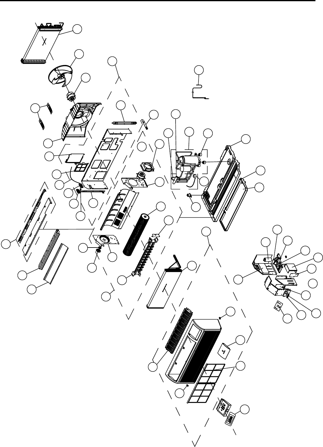
2011 PTAC EXPLODED VIEW
50
1
17
16
36
24
53
54
45
25
41
40
9
48
8
44
51
49
43
6
38
20
37
18
2
4
5
12
52
34
42
32
33
31
30
47
23
21
50
19
46
7
11
39
28
15
14
29
27
55
56
57
10
13
3
36
26
35
22

PDE07K3SF
PDE07R3SF
PDE09K3SF
PDE09R3SF
PDE12K3SF
PDE12R3SF
PDE15K5SF
PDE15R5SF
Ref. # Description Qty Part # Part # Part # Part # Part # Part # Part # Part #
1 Air Filter (Pair) 2
68700138 68700138 68700138 68700138 68700138 68700138 68700138 68700138
Air Guide 1
68700055 68700056 68700057 68700058 68700082 68700083 68700082 68700083
* Ambient Temperature Sensor 1
68700152 68700152 68700152 68700152 68700152 68700152 68700152 68700152
3 Basepan 1
68700096 68700096 68700015 68700096 68700097 68700097 68700077 68700077
4 Bearing Cap 1
68700127 68700127 68700127 68700127 68700127 68700127 68700127 68700127
5 Bearing Support, Rubber sub-assy 1
68700147 68700147 68700147 68700147 68700147 68700147 68700147 68700147
6 Bellows Drain Valve 1
68700134 68700134 68700134 68700134 68700134 68700134 68700134 68700134
7 Bottom Inner Wall Brace 1
68700118 68700118 68700118 68700118 68700118 68700118 68700118 68700118
8 Capacitor 1
68700100 68700100 68700107 68700100 68700107 68700107 68700044 68700107
9 Capacitor, Fan 1
68700113 68700113 68700113 68700113 68700109 68700108 68700109 68700109
9 Capacitor, Fan 1
68700091 68700108 68700091 68700108 68700113 68700109 68700113 68700108
10 Capillary Tube Assy 1
68700085 68700085 68700017 68700016 68700084 68700084 68700059 68700059
11 Chassis Flange, Right 1
68700124 68700124 68700124 68700124 68700124 68700124 68700124 68700124
12 Chassis Flange, Left 1
68700125 68700125 68700125 68700125 68700125 68700125 68700125 68700125
13 Compressor Assy 1
68700050 68700049 68700001 68700004 68700047 68700048 68700005 68700006
14 Condenser Coil 1
68700081 68700081 68700102 68700102 68700102 68700102 68700080 68700080
15 Condenser Fan Blade 1
68700135 68700135 68700135 68700135 68700135 68700135 68700135 68700135
16 Control Door 1
68700145 68700145 68700145 68700145 68700145 68700145 68700145 68700145
17 Control Panel Overlay Escutcheon 1
68700158 68700158 68700158 68700158 68700158 68700158 68700158 68700158
18 Cross flow fan support, left 1
68700129 68700129 68700129 68700129 68700129 68700129 68700129 68700129
19 Cross flow fan support, right 1
68700130 68700130 68700130 68700130 68700130 68700130 68700130 68700130
20 Cross Flow Fan, Evaporator 1
68700136 68700136 68700136 68700136 68700136 68700136 68700136 68700136
21 Deck 1
68700131 68700131 68700131 68700131 68700131 68700131 68700131 68700131
22 Discharge Grille 1
68700143 68700143 68700143 68700143 68700143 68700143 68700143 68700143
23 Discharge Screen 1
68700122 68700122 68700122 68700122 68700122 68700122 68700122 68700122
24 Display Board 1
68700151 68700151 68700151 68700151 68700151 68700151 68700151 68700151
25 Electric Box Assy 1
68700028 68700030 68700032 68700034 68700036 68700038 68700040 68700042
26 Evaporator Coil 1
68700079 68700079 68700014 68700013 68700101 68700101 68700101 68700101
27 Evaporator Foam Drain Tray 1
68700141 68700141 68700141 68700141 68700141 68700141 68700141 68700141
28 Fan Motor, Condenser 1
68700087 68700088 68700087 68700088 68700078 68700086 68700078 68700086
29 Fan Motor, Evaporator 1
68700072 68700073 68700070 68700071 68700089 68700090 68700089 68700090
30 Fan Shroud + Motor Mount 1
68700137 68700137 68700137 68700137 68700137 68700137 68700137 68700137
31 Fresh Air Door 1
68700121 68700121 68700121 68700121 68700121 68700121 68700121 68700121
32 Fresh Air Door Cable 1
68700133 68700133 68700133 68700133 68700133 68700133 68700133 68700133
33 Fresh Air Door Filter 1
68700139 68700139 68700139 68700139 68700139 68700139 68700139 68700139
34 Fresh Air Door Lever 1
68700148 68700148 68700148 68700148 68700148 68700148 68700148 68700148
35 Front Panel Assy (Complete) 1
68700144 68700144 68700144 68700144 68700144 68700144 68700144 68700144
36 Front Panel clip 2
68700128 68700128 68700128 68700128 68700128 68700128 68700128 68700128
37 Heater 1
68700074 68700075 68700098 68700099 68700098 68700099 68700098 68700099
38 Heater Wiring Block Board 1
68700126 68700126 68700126 68700126 68700126 68700126 68700126 68700126
39 Inner Wall assy 1
68700115 68700115 68700115 68700115 68700115 68700115 68700115 68700115
40 Junction box 1
68700120 68700120 68700120 68700120 68700120 68700120 68700120 68700120
41 Junction lid 1
68700117 68700117 68700117 68700117 68700117 68700117 68700117 68700117
42 Lower cover of Fresh Air Door Lever 1
68700150 68700150 68700150 68700150 68700150 68700150 68700150 68700150
44 Relay board 1
68700105 68700105 68700105 68700105 68700105 68700105 68700105 68700105
45 Logic board 1
68700103 68700104 68700103 68700104 68700103 68700104 68700103 68700104
46 Motor Bracket, Indoor 1
68700123 68700123 68700123 68700123 68700123 68700123 68700123 68700123
* Overload Protector 1
68700052 68700051 n/a 68700162 68700053 68700161 68700010 68700009
47 Shroud Brace 2
68700119 68700119 68700119 68700119 68700119 68700119 68700119 68700119
* Temperature Sensor 1
68700110 68700110 68700110 68700110 68700110 68700110 68700110 68700110
48 Terminal Board, Input power 2
68700156 68700156 68700156 68700156 68700156 68700156 68700156 68700156
49 Thermal baffle 1
68700132 68700132 68700132 68700132 68700132 68700132 68700132 68700132
50 Top Cover Plate Sub-Assy 1
68700116 68700116 68700116 68700116 68700116 68700116 68700116 68700116
51 Transformer 1
68700112 68700111 68700112 68700111 68700112 68700111 68700112 68700111
* Tube Thermistor 1
68700153 68700153 68700153 68700153 68700153 68700153 68700153 68700153
52 Upper cover of Fresh Air Door Lever 1
68700149 68700149 68700149 68700149 68700149 68700149 68700149 68700149
53 Wiring Terminal, 2 position 24VAC 1
68700154 68700154 68700154 68700154 68700154 68700154 68700154 68700154
54 Wiring Terminal, 7 position 24VAC 1
68700155
68700046 68700046 68700046 68700046 68700046 68700046
68700155 68700155 68700155 68700155 68700155 68700155 68700155
55 Compressor Grommets 3
68700046 68700076
2011 PTAC PARTS LIST - PDE MODELS
51

PDH07K3SF
PDH07R3SF
PDH09K3SF
PDH09R3SF
PDH12K3SF
PDH12R3SF
PDH15K5SF
PDH15R5SF
Ref. # Description Qty Friedrich # Friedrich # Friedrich # Friedrich # Friedrich # Friedrich # Friedrich # Friedrich #
1 Air Filter (Pair) 2
68700138 68700138 68700138 68700138 68700138 68700138 68700138 68700138
2 Air Guide 1
68700055 68700056 68700057 68700058 68700082 68700083 68700082 68700083
* Ambient Temperature Sensor 1
68700152 68700152 68700152 68700152 68700152 68700152 68700152 68700152
3 Basepan 1
68700096 68700096 68700097 68700097 68700097 68700097 68700160 68700077
4 Bearing Cap 1
68700127 68700127 68700127 68700127 68700127 68700127 68700127 68700127
5 Bearing Support, Rubber sub-assy 1
68700147 68700147 68700147 68700147 68700147 68700147 68700147 68700147
6 Bellows Drain Valve 1
68700134 68700134 68700134 68700134 68700134 68700134 68700134 68700134
7 Bottom Inner Wall Brace 1
68700118 68700118 68700118 68700118 68700118 68700118 68700118 68700118
8 Capacitor 1
68700100 68700100 68700107 68700100 68700107 68700107 68700043 68700107
9 Capacitor, Fan 1
68700113 68700113 68700113 68700113 68700109 68700108 68700109 68700109
9 Capacitor, Fan 1
68700091 68700108 68700091 68700108 68700113 68700109 68700113 68700108
10 Capillary Tube Assy 1
68700085 68700085 68700060 68700060 68700084 68700084 68700018 68700019
11 Chassis Flange, Left 1
68700124 68700124 68700124 68700124 68700124 68700124 68700124 68700124
12 Chassis Flange, Right 1
68700125 68700125 68700125 68700125 68700125 68700125 68700125 68700125
13 Compressor Assy 1
68700050 68700049 68700002 68700003 68700047 68700048 68700007 68700008
14 Condenser Coil 1
68700081 68700081 68700102 68700102 68700102 68700102 68700080 68700080
15 Condenser Fan Blade 1
68700135 68700135 68700135 68700135 68700135 68700135 68700135 68700135
16 Control Door 1
68700145 68700145 68700145 68700145 68700145 68700145 68700145 68700145
17 Control Panel Overlay Escutcheon 1
68700158 68700158 68700158 68700158 68700158 68700158 68700158 68700158
18 Cross flow fan support, left 1
68700129 68700129 68700129 68700129 68700129 68700129 68700129 68700129
19 Cross flow fan support, right 1
68700130 68700130 68700130 68700130 68700130 68700130 68700130 68700130
20 Cross Flow Fan, Evaporator 1
68700136 68700136 68700136 68700136 68700136 68700136 68700136 68700136
21 Deck 1
68700131 68700131 68700131 68700131 68700131 68700131 68700131 68700131
22 Discharge Grille 1
68700143 68700143 68700143 68700143 68700143 68700143 68700143 68700143
23 Discharge Screen 1
68700122 68700122 68700122 68700122 68700122 68700122 68700122 68700122
24 Display Board 1
68700151 68700151 68700151 68700151 68700151 68700151 68700151 68700151
25 Electric Box Assy 1
68700029 68700031 68700033 68700035 68700037 68700039 68700041 68700027
26 Evaporator Coil 1
68700079 68700079 68700054 68700054 68700101 68700101 68700101 68700101
27 Evaporator Foam Drain Tray 1
68700141 68700141 68700141 68700141 68700141 68700141 68700141 68700141
28 Fan Motor, Condenser 1
68700087 68700088 68700087 68700088 68700078 68700086 68700089 68700086
29 Fan Motor, Evaporator 1
68700072 68700073 68700070 68700071 68700089 68700090 68700026 68700090
30 Fan Shroud + Motor Mount 1
68700137 68700137 68700137 68700137 68700137 68700137 68700137 68700137
31 Fresh Air Door 1
68700121 68700121 68700121 68700121 68700121 68700121 68700121 68700121
32 Fresh Air Door Cable 1
68700133 68700133 68700133 68700133 68700133 68700133 68700133 68700133
33 Fresh Air Door Filter 1
68700139 68700139 68700139 68700139 68700139 68700139 68700139 68700139
34 Fresh Air Door Lever 1
68700148 68700148 68700148 68700148 68700148 68700148 68700148 68700148
35 Front Panel Assy (Complete) 1
68700144 68700144 68700144 68700144 68700144 68700144 68700144 68700144
36 Front Panel clip 2
68700128 68700128 68700128 68700128 68700128 68700128 68700128 68700128
37 Heater 1
68700074 68700075 68700098 68700099 68700098 68700099 68700098 68700099
38 Heater Wiring Block Board 1
68700126 68700126 68700126 68700126 68700126 68700126 68700126 68700126
39 Inner Wall assy 1
68700115 68700115 68700115 68700115 68700115 68700115 68700115 68700115
40 Junction box 1
68700120 68700120 68700120 68700120 68700120 68700120 68700120 68700120
41 Junction lid 1
68700117 68700117 68700117 68700117 68700117 68700117 68700117 68700117
42 Lower cover of Fresh Air Door Lever 1
68700150 68700150 68700150 68700150 68700150 68700150 68700150 68700150
43 Solenoid Coil 1
68700093 68700092 68700093 68700092 68700093 68700092 68700093 68700092
44 Relay board 1
68700106 68700106 68700106 68700106 68700106 68700106 68700106 68700106
45 Logic board 1
68700103 68700104 68700103 68700104 68700103 68700104 68700103 68700104
46 Motor Bracket, Indoor 1
68700123 68700123 68700123 68700123 68700123 68700123 68700123 68700123
* Overload Protector 1
68700052 68700051 68700012 n/a 68700053 n/a n/a 68700011
47 Shroud Brace 2
68700119 68700119 68700119 68700119 68700119 68700119 68700119 68700119
48 Terminal Board, Input power 2
68700156 68700156 68700156 68700156 68700156 68700156 68700156 68700156
49 Thermal baffle 1
68700132 68700132 68700132 68700132 68700132 68700132 68700132 68700132
50 Top Cover Plate Sub-Assy 1
68700116 68700116 68700116 68700116 68700116 68700116 68700116 68700116
51 Transformer 1
68700112 68700111 68700112 68700111 68700112 68700111 68700112 68700111
* Tube Thermistor 2
68700153 68700153 68700153 68700153 68700153 68700153 68700153 68700153
52 Upper cover of Fresh Air Door Lever 1
68700149 68700149 68700149 68700149 68700149 68700149 68700149 68700149
53 Wiring Terminal, 2 position 24VAC 1
68700154 68700154 68700154 68700154 68700154 68700154 68700154 68700154
54 Wiring Terminal, 7 position 24VAC 1
68700155 68700155 68700155 68700155 68700155 68700155 68700155 68700155
55 Compressor Gasket 3
n/a n/a n/a n/a n/a n/a 68700045 68700076
56 4-way Reversing Valve Assy 1
68700094 68700094 68700094 68700094 68700095 68700095 68700095 68700095
56 4-way Reversing Valve Assy 1
68700062 68700062 68700063 68700063 68700061 68700061 68700020 68700021
52
2011 PTAC PARTS LIST - PDH MODELS

FRIEDRICH AIR CONDITIONING CO.
10001 Reunion Place, Ste. 500, San Antonio, TX 78216
P 210-546-0500 | F 210-546-0731
www.friedrich.com
Printed in the U.S.A.
PD-ServMan-E (2-11)
