EZ Series VP & EZ Series VR (DR. VTAC option)
Perfect t for Replacing Existing GE 8500 & 7500 Series
Friedrich Vertical and for New Construction Projects
Engineering Manual
MANUFACTURER OF QUALITY AIR CONDITIONING AND HEATING PRODUCTS
6140278 Rev. J 03/19/18

Manufacturer of Quality Air Conditioning and Heating Products • www.islandaire.com • sales@islandaire.com • (800)-886-2759
2
Table of Contents
Islandaire reserves the right to make changes in design and construction at any time without notice.
INSTALLATION INSTRUCTIONS CASE
& CHASSIS ....................................................................21
Unit including case and chassis .....................................21
INSTALLATION INSTRUCTIONS DRAINS ............. 22
Drain Connection(s) .....................................................22
INSTALLATION INSTRUCTIONS POWER
CORD, DUCT .............................................................. 23
Unit Power Connection ................................................. 23
Voltage Measurements ...................................................23
Connect the Top Duct ................................................... 23
INSTALLATION INSTRUCTIONS THERMOSTAT .24
Remote Wall Mounted ermostat ............................... 24
Wireless Wall Mounted ermostat ..............................24
Remote ermostat Interface ........................................25
INSTALLATION INSTRUCTIONS INTERIOR
GRILLE .......................................................................... 26
Interior Return Air Grille .............................................. 26
WIRING DIAGRAMS ....................................................27
SYSTEM CONTROLS AND MANAGEMENT .............. 29
USER INTERFACES ...................................................... 29
Wall ermostats ........................................................... 29
Front Desk Control ........................................................ 29
Controls Logic ............................................................... 30
Room Freeze Prevention ............................................... 30
High Temperature Compressor Protection .................. 30
Low Temperature Compressor Protection .................... 30
Diagnostic Soware .......................................................30
Custom Operation and Continual Room
Temperature Monitoring .............................................. 30
Operating Guidelines ....................................................31
MAIN CONTROL BOARD .......................................... 32
PERFORMANCE SPECIFICATIONS ...........................33
Vertical Packaged Terminal Cooling Unit With
Heat Pump Or Electric Heating ...................................33
TYPICAL WARRANTY ................................................. 36
EZ REPLACEMENT GUIDE ..........................................37
INTRODUCTION ..........................................................3
Our Company ................................................................ 3
e Perfect Fit ................................................................ 3
APPLICATIONS .............................................................4
New Construction ..........................................................4
Advantages For New Construction ............................... 4
Retrot/Replacement .................................................... 4
Application Considerations ..........................................5
Undersizing ....................................................................5
Oversizing ...................................................................... 5
Air Inltration ............................................................... 5
Guaranteed Quality ....................................................... 5
Indoor Air Quality - DR.VTAC .....................................5
PRODUCT OVERVIEW ................................................ 6
Quiet Operation ............................................................ 6
Durable Construction ...................................................6
Corrosion Protection ..................................................... 6
CHASSIS FEATURES AND BENEFITS ........................ 7
Slide Out Chassis – ........................................................ 7
Wall Plenum – ................................................................7
Exterior Louver/Grilles – .............................................. 7
Removable Access Panel – .............................................7
Slinger Fan – ..................................................................7
Venturi Shroud – ........................................................... 7
EZ SERIES VP DATA ...................................................... 8
Model Nomenclature ..................................................... 8
Performance Data for EZ Series VP .............................. 9
Heating options ............................................................. 9
Electrical ........................................................................9
EZ SERIES VR DATA ...................................................... 10
Model Nomenclature ..................................................... 10
Performance Data for EZ Series VR ..............................11
Heating options ............................................................. 11
Electrical ........................................................................11
PRODUCT INFORMATION .........................................12
Heat Pump Features ...................................................... 13
DIMENSIONAL DRAWINGS ........................................ 14
INSTALLATION INSTRUCTIONS WALL PLENUM 17
Wall Plenum ...................................................................17
INSTALLATION INSTRUCTIONS EXTERIOR
GRILLE .......................................................................... 18
Standard exterior (Rear) Grille ..................................... 18
Architectural Exterior (Rear) Grille ............................. 19
INSTALLATION INSTRUCTIONS BASE
PLATFORM ................................................................... 20
Base Platform Construction .......................................... 20

Manufacturer of Quality Air Conditioning and Heating Products • www.islandaire.com • sales@islandaire.com • (800)-886-2759
3
Our Company
Islandaire is the fastest growing specialty air conditioning and heat-
ing manufacturer in the country. Founded in 1992 by Robert Hansen,
it has grown into a multi-million dollar company in just a few short
years. Islandaire builds a full complement of high quality thru-the-
wall replacement air conditioners and heat pumps, water source heat
pumps, and gas units in East Setauket, New York. Each model ts per-
fectly into the existing original wall case assembly, thereby saving both
time and money during installations.
Our Engineering, Production, Sales and Customer Service depart-
ments have been fully integrated to provide the maximum degree
of user satisfaction. We at Islandaire feel that this team approach to
manufacturing produces a superior overall product and assures a larger
degree of exibility in design and production scheduling to meet tight
prototyping or construction timetables.
The Perfect Fit
ru-wall air conditioners were developed in the late 1950’s. Over
the next forty years many companies engineered, manufactured and
installed a variety of dierent units throughout the United States and
Canada. Today, a number of these companies are no longer in business
or have discontinued their line of thru-wall air conditioners and no
longer carry replacement parts.
Islandaire oers replacement air conditioners and heat pumps that are
interchangeable with units no longer available from the original manu-
facturer. Our units are engineered to t perfectly within the existing
wall case, thereby reducing installation time and expense. ey are
manufactured at our modern 75,000 square foot plant on Long Island
in New York.
ank you for considering our products,
e Islandaire Team
Introduction

Manufacturer of Quality Air Conditioning and Heating Products • www.islandaire.com • sales@islandaire.com • (800)-886-2759
4
Applications
ADVANTAGES FOR NEW CONSTRUCTION
• Lower Operating Costs and Reliable Comfort
for the Occupant
• Design Flexibility For e Architect/Engineer
• Super-quiet performance, indoors and out
• No bulky duct system needed
• No separate equipment room
• No water towers or additional cooling equip-
ment
• Optional architectural grille to permit custom
exterior appearance
Islandaire helps lower utility costs with energy e-
cient units that exceed industry standards. Energy
savings are achieved in both heating and cooling
environments through ecient mechanical design
and onboard electronic logic. Separate indoor and
outdoor fans provide lower operating costs. Energy
management capability is built into the unit’s stan-
dard digital controls.
ese units may also qualify for electrical power
company rebates. Consult your local utility provider
for rebate opportunities.
Retrofit/
Replacement
Islandaire VTAC units are engineered to t per-
fectly within existing GE wall cases, thereby reduc-
ing installation time and expense. ere is no time
wasted on redesigning an existing wall opening or
removing an old wall case. Just slide the old chassis
out and replace with a new one from Islandaire.
Our EZ Quick slide-out chassis eases installation
into the wall case. Rapid servicing reduces down-
time; the complete chassis can be replaced in min-
utes without disrupting other occupants.
e EZVP and EZVR Series vertical terminal air
conditioning (VTAC) units are designed and manu-
factured for new construction or the replacement of
units in an existing building. Our VTAC units pro-
vide year-round comfort control for hotels, motels,
apartments, dormitories, shops, nursing homes,
assisted living centers, satellite oces, room addi-
tions and other applications that require economical
heating and cooling.
e product is designed for individually-zoned,
comfort-controlled heating and cooling. We oer
our cooling chassis to operate with cooling only or
electric heat. e design standards, heavy duty con-
struction and the focus on indoor noise reduction
has established our product as the premier unit of
the future. Individually controlled VTAC units are
ideal for rooms that are not occupied, such as during
vacancies, holidays, weekends or nights. Individual
units permit tenants to choose their own degree of
comfort and operating economy.
Temperature and fan settings are controlled via wall
thermostat. In addition, all units have the ex-
ibility of working with controls that integrate with
an energy management system. Whether you are
designing a new structure or replacing VTAC units
in an existing building, Islandaire will meet your
needs.
New Construction
e Islandaire VTAC unit is designed to meet the
needs of the architect, engineer, and contractor. For
unit installation, Islandaire’s expert support network
will assist in all applicable aspects of the construc-
tion project, from preparing a budget to start-up.
Manufacturer of Quality Air Conditioning and Heating Products • www.islandaire.com • sales@islandaire.com • (800)-886-2759
5
Applications (Cont.)
Guaranteed Quality
Each Islandaire unit is designed to operate quietly
and eciently and is backed by the best warranty
program available. Standard warranty is for one
year parts and labor including ve year compressor
part only warranty, or two year parts only including
ve year compressor part only warranty.
Whether it is an exact replacement unit or a new
construction project, Islandaire is the smart choice
for all your air conditioning and heating needs.
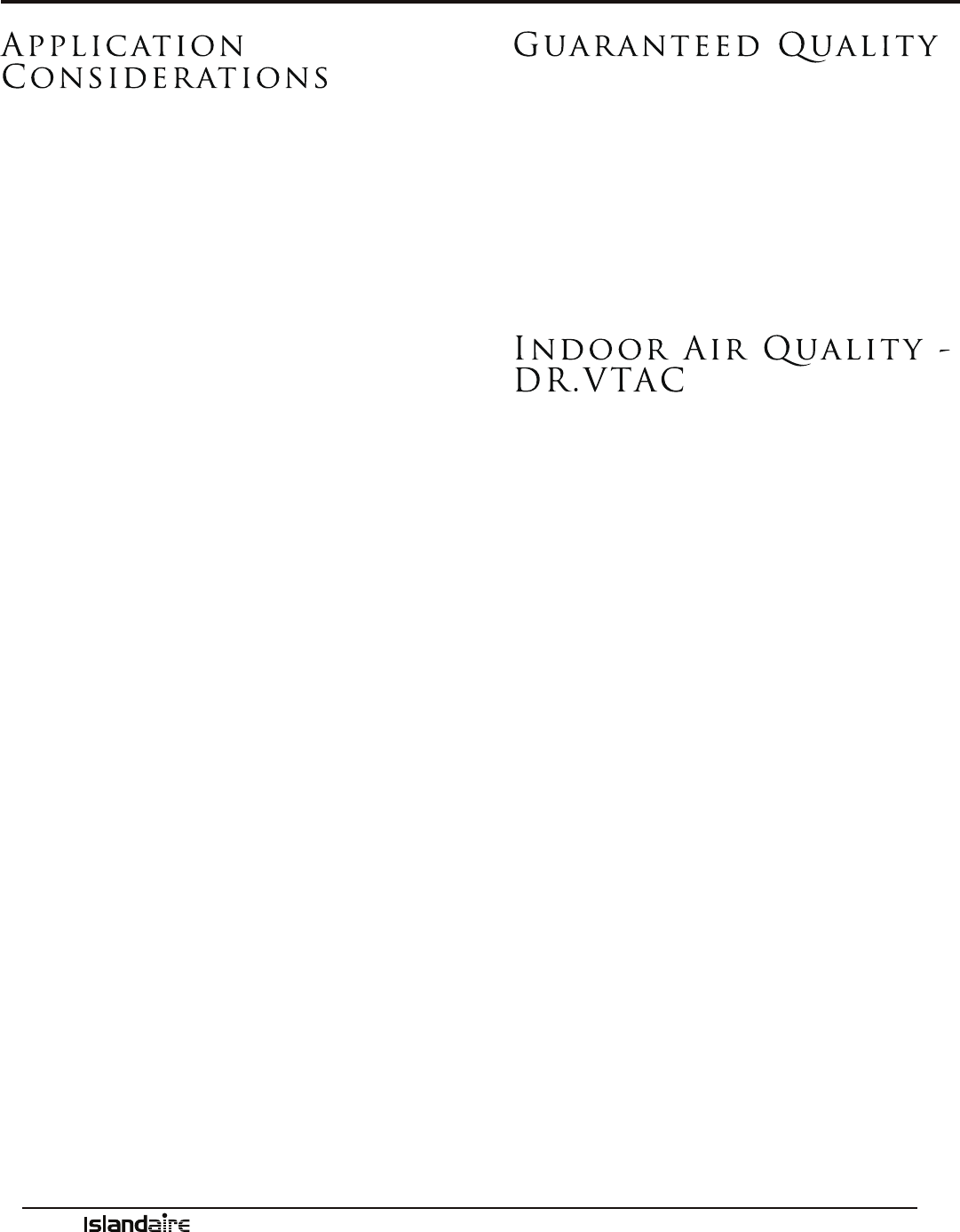
Indoor Air Quality -
DR.VTAC
In addition to an already quiet unit, we have
developed an indoor air quality option called the
DR.VTAC.
DR.VTAC is a two-stage system. e primary stage
conditions room air and tempers the air to accept-
able air quality levels. e secondary stage brings in
conditioned outside air at a rate of up to 75 CFM, to
compensate for toilet exhaust and room occupancy,
and continuously pressurizes the room. e sec-
ondary stage is initiated by an outdoor humidistat
that allows the unit to condition the incoming fresh
air to about 55% RH. e system can be calibrated
to run at higher outdoor RH levels, but the recom-
mended maximum set point is 55% outdoor RH.
When outdoor RH levels are above the set point, the
secondary compressor is initiated and conditions
make up air.
e secondary fan continuously runs allowing fresh,
conditioned, make-up air at a rate of up to 75 CFM
(leaving coil CFM) to enter the room. e unit is
manufactured in accordance to AHRI, UL, CSA
standards for the primary side and AHAM and UL
standards for the secondary side.
Application
Considerations
It is important for air conditioning systems to
be properly sized for each application in order to
achieve desired temperature and humidity levels. It
is strongly recommended that a professional engi-
neer match the VTAC units with the building struc-
ture and regional climate.
e following application considerations are all
important in choosing the proper VTAC system for
the building structure.
UNDERSIZING
If a VTAC unit is undersized (cooling capacity is
less than required capacity for the specic applica-
tion), the unit will not be able to cool the space
down to the desired temperature during very hot
days, causing excessive power consumption.
OVERSIZING
If a VTAC unit is oversized (cooling capacity is
greater than required capacity for the specic appli-
cation), the unit will cool the space down to the
desired temperature too quickly, creating a cool yet
excessively humid space.
AIR INFILTRATION
Excessive air inltration can intensify problems
associated with undersizing or oversizing a VTAC
unit. is can be the cause of insucient cooling,
dehumidication, or heating. Sources of air inltra-
tion include vents, gaps around windows and doors,
and improperly sealed oors, ceiling or wall joints.

Manufacturer of Quality Air Conditioning and Heating Products • www.islandaire.com • sales@islandaire.com • (800)-886-2759
6
Product Overview
Corrosion
Protection
All Islandaire VTAC units have special corrosion
protection that can help dramatically extend the life
of the unit. Listed below are just some of the com-
ponents that feature corrosion protection:
• Wall Case - e entire wall case is constructed
of 18-gauge galvanized steel.
• Base Pan - e base pan is constructed of
18-gauge galvanized steel with powder coat
paint nish to protect it from the elements.
• Condenser Fan Blade - Constructed of strong
engineered plastic that has excellent ame-
resistance and dimensional stability over a wide
range of service temperatures.
• Condenser Fan Motor - Specially coated by the
manufacturer to resist corrosion.
• Compressor - Protectively-coated exterior to
enhance equipment life and performance.
• Outdoor Louver - Made of aluminum, etched
and anodized for maximum corrosion protec-
tion. Available in various architectural styles.
Can be painted in a wide choice of colors.
Quiet Operation
e VTAC unit provides whisper quiet operation
while delivering maximum airow required for
proper air circulation. Separate indoor and out-
door fan motors further reduce operating sound
levels and costs.
e heavy gauge construction of the chassis and
cabinet minimizes vibration for quieter operation.
Vibration isolators on the rotary compressor keep
it running smoothly and quietly. e unit bulk-
head is fully insulated to decrease outdoor sound
transmission.
Durable
Construction
• Islandaire VTAC units are built with durable
quality components designed for continuous
operation in all environments.
• Our wall cases are constructed of 18-gauge
thick galvanized steel for maximum durability.
• e outdoor fan motor is totally enclosed,
preventing damage from moisture and debris
introduced by extreme weather conditions.
Both indoor and outdoor fan motors are per-
manently lubricated for extended life.
• Electrical components are located on the
indoor side of the wall protecting them from
driving rain and humidity.
• e compressor is a reliable, high-eciency
design rotary compressor. It is hermetically
sealed and built for continuous operation.
Manufacturer of Quality Air Conditioning and Heating Products • www.islandaire.com • sales@islandaire.com • (800)-886-2759
7
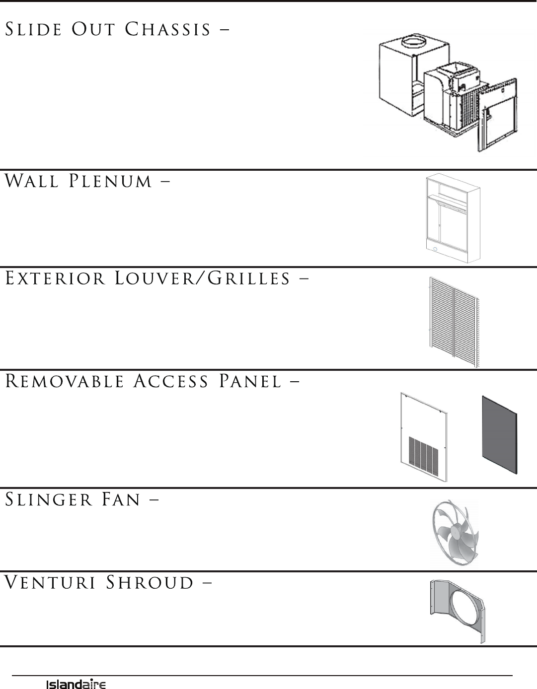
Slide Out Chassis –
• Slide-out chassis makes installation simple
• All components are readily accessible to service personnel
• On-board diagnostic soware and display help diagnose potential
problems
• Designed to replace older units with minimal modication
• Isolated rotary compressor design for continuous ecient, reliable
and quiet operation
See page 21 for chassis installation instructions
Wall Plenum –
• Heavy 18 gauge steel with powder paint coating for maximum
scratch, dent and corrosion resistance
• Optional wall depths of 6”, 8”, 10”, 12”, and 15” available
See page 17 for wall plenum installation instructions
Exterior Louver/Grilles –
• Architectural extruded aluminum grille
• Custom colors available (Ask for our color chart sheet)
• Recessed available
See page 18 for exterior grille installation instructions
Removable Access Panel –
• Made from durable, powder-coated metal that won’t rust, resists
scratches and is easy to clean
• Quick removal ensures shorter installation time and faster service
calls
• Easy access to removable lters
• Optional Sound-Reduction Grille for quieter operation
Slinger Fan –
• Curved fan blades increase airow across the outside coil
• Creates a quiet operating environment outside of building
• Slinger ring eciently removes condensate and increases cooling
Venturi Shroud –
• Works with the fan to maximize air ow and increase eciency
• Removes easily for quick access when cleaning the condenser coil
Chassis Features and Benefits

Manufacturer of Quality Air Conditioning and Heating Products • www.islandaire.com • sales@islandaire.com • (800)-886-2759
8
EZ Series VP Data
Model Nomenclature
Please review the nomenclature/model number
breakdown below for the EZ Series VP options.
Units are available in four cooling BTUh capaci-
ties: 9,000; 12,000; 15,000; 18,000
Voltage options are: 208/230V or 277V
Control choices include multiple-wired, wall-
mounted heating/cooling thermostats and a wireless
wall thermostat, with occupancy sensor control.
FEATURES: ACCESSORIES:
•18 gauge galvanized, powder-coat
painted wall plenum
•Motion sensor/door switch
capable
•Superior temperature control
•Dehumidication of room air
•Wall thermostat required
•Compressor freeze protection
•Self diagnosis
•Random Auto Re-start
•Compressor time delay
•Front desk control capable
•Room side freeze protection
•Motorized fresh air damper
•Power disconnect
•High pressure cutout
•Wired remote thermostat
•Wireless remote thermostat
•Energy Management ermostat
•I.R. motion sensor
•Door switch
•Access Panel (louvered, non-
louvered, and sound-reduction
types)
•Return Air Grille
OPTIONS:
•Architectural Louver
COMPONENT
EZ - Cooling Chassis
MODEL TYPE
VP - Islandaire Vertical Unit
COOLING CAPACITY
09 - 9,000 BTU
12 - 12,000 BTU
15 - 15,000 BTU
18 - 18,000 BTU
VOLTAGE / LINE CORD
2 - 230V 20 Amps
3 - 230V 30 Amps
4 - 230V Junction Box
7 - 277 V 20 Amps
8 - 277 V Junction Box
9 - 230V 15 Amps
F - 277V 30 Amps
HEATING OPTIONS
A - None, Cooling Only
B - 2.5 KW Electric Heat
C - 3.6 KW Electric Heat
E - 5.0 KW Electric Heat*
*5.0 KW heat available on
15 & 18 kBTU units only
ROOM CONTROLS
1- None
N - Standard Electronic Control Remote
Thermostat
FUNCTIONAL OPTIONS
B- Motorized Fresh Air Damper
POWER MANAGEMENT OPTIONS
A- None
C- Energy Mgt. N/O
D- Energy Mgt. N/C
IDENTITY CODE
0 - Special
5 - Standard
RETURN DISCHARGE OPTIONS
4 - Front Return/Top Discharge
EZ VP 12 A 2 C 1 N 4 5 A B
HYDRONIC OPTIONS
SYSTEM TYPE
A - Standard Chassis (R410A)
B - Heat Pump (R410A)
Manufacturer of Quality Air Conditioning and Heating Products • www.islandaire.com • sales@islandaire.com • (800)-886-2759
9
EZ Series VP Data (Cont.)
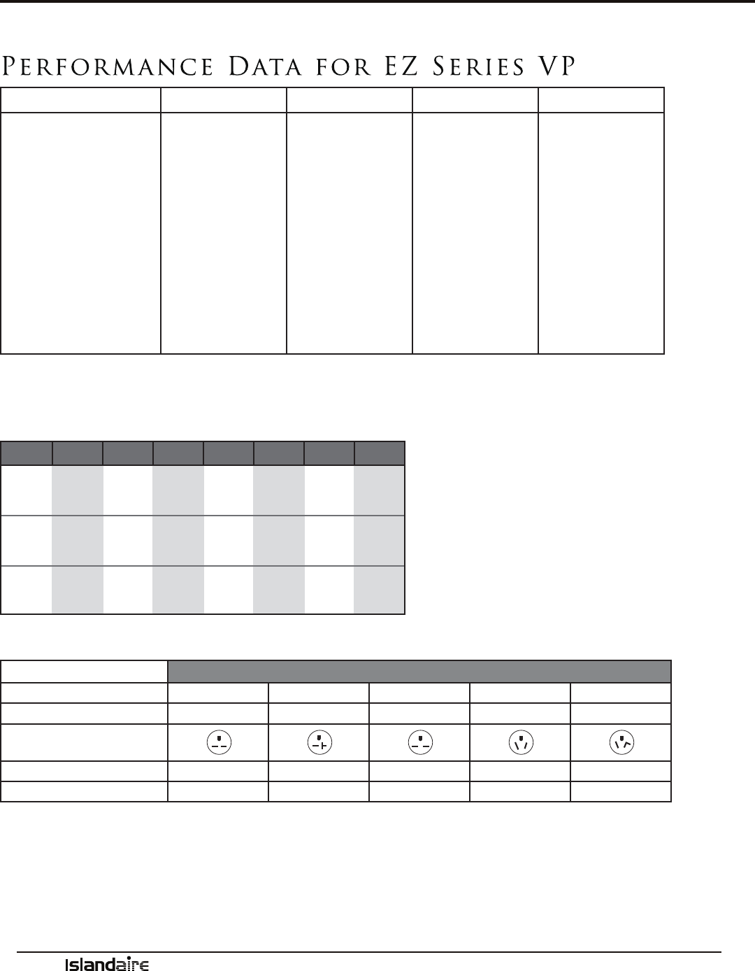
Performance Data for EZ Series VP
EZ09 EZ12 EZ15 EZ18
VOLTS 208-230 265-277 208-230 265-277 208-230 265-277 208-230 265-277
COOLING BTUH 8900 8900 11700 11700 14800 14800 17500 17500
COOLING LATENT BTUH 2225 2225 2925 2925 3700 3700 4375 4375
COOLING SENSIBLE BTUH 6675 6675 8775 8775 11100 11100 13125 13125
AMPS 3.87 3.21 5.09 4.22 6.43 5.34 7.61 6.32
COOLING WATTS 890 890 1170 1170 1480 1480 1750 1750
EER 10 10 10 10 10 10 10 10
CFM HIGH SP 0.1” 424 424 482 482 532 532 565 565
CFM LOW SP 0.1” 370 370 421 421 475 475 525 525
HEATING BTUH 8400 8400 10900 10900 13400 13400 15500 15500
HEATING WATTS 820 820 1065 1065 1309 1309 1514 1514
COP 3 3 3 3 3 3 3 3
Heating capacities specied in accordance with ANSI/AHRI standard 390 at conditions of 47 °F DB/43 °F WB outdoor and 70 °F DB/60 °F WB indoor. Wattage, amperage, COP, EER listings include compressor,
evaporator motor and condenser fan motor. Cooling capacities specied in accordance with ANSI/AHRI standard 390 at conditions of 95 °F DB/75 °F WB outdoor and 80 °F/67 °F WB indoor.
HEATING OPTIONS
Heating
Option
Voltage (1) Wattage B.T.U.s (2) Amps (3) MCA (4) MOP (Amps) Power Cord
B
208
230
277
2,050
2,500
2,500
7,000
8,535
8,535
10.46
11.47
9.63
13.1
14.3
12.0
15
15
15
6-15
6-15
7-20
C
208
230
277
2,950
3,600
3,600
10,070
12,290
12,290
14.78
16.25
13.60
18.5
20.3
17.0
20
20
20
6-20
6-20
7-20
E
208
230
277
4,100
5,000
5,000
14,000
17,070
17,070
20.31
22.34
18.65
25.4
27.9
23.3
30
30
30
6-30
6-30
7-30
(1) Voltage is 60Hz, Single Phase, Alternating Current and R.M.S. (2) Heating Capacity (B.T.U./Hr.) based on indoor
blower motor and heating elements. (3) Amp values are a combination of indoor blower motor and heating elements.
ELECTRICAL
EZVR
LINE VOLTAGE 208/230 208/230 208/230 277 277
MAXIMUM AMPERAGE 12 16 24 16 24
WALL SOCKET CONFIGURATION
RECEPTACLE NUMBER NEMA 6-15R NEMA 6-20R NEMA 6-30R NEMA 7-20R NEMA 7-30R
ELECTRICAL HEAT OPTIONS 2.5 2.5 - 3.6 4.2 - 5.0 2.5 - 4.2 2.5 - 4.2
* All data is subject to change

Manufacturer of Quality Air Conditioning and Heating Products • www.islandaire.com • sales@islandaire.com • (800)-886-2759
10
Model Nomenclature
Please review the nomenclature/model number
breakdown below for the EZ Series VR options.
Units are available in four cooling BTUH capaci-
ties: 9,000; 12,000; 15,000; 18,000
EZ Series VR Data
Voltage options are: 208/230V or 277V
Control choices include multiple-wired, wall
mounted heating/cooling thermostats and a wireless
wall thermostat, with occupancy sensor control
HYDRONIC OPTIONS
MODEL TYPE
VR - DR. VTAC
VOLTAGE / LINE CORD
2 - 230V 20 Amps
3 - 230V 30 Amps
4 - 230V Junction Box
7 - 277 V 20 Amps
8 - 277 V Junction Box
9 - 230V 15 Amps
F - 277V 30 Amps
COMPONENT
EZ - Cooling Chassis
COOLING CAPACITY
09 - 9,000 BTU
12 - 12,000 BTU
15 - 15,000 BTU
18 - 18,000 BTU
SYSTEM TYPE
A- Standard Chassis (R410A)
B - Heat Pump (R410A)
HEATING OPTIONS
A - None, Cooling Only
B - 2.5 KW Electric Heat
C - 3.6 KW Electric Heat
E - 5.0 KW Electric Heat *
*5.0 KW heat available on
15 & 18 kBTU units only
ROOM CONTROLS
1- None
N - Standard Electronic Control
Remote Thermostat
FUNCTIONAL OPTIONS
A - None
B - Dehum-heater 250w
C - Dehum-heater 400w
POWER MANAGEMENT OPTIONS
A - None
P - Energy Mgt. N/O
T - Energy Mgt. N/C
IDENTITY CODE
0 - Special
5 - Standard
RETURN DISCHARGE OPTIONS
4 - Front Return/Top Discharge
EZ VR 12 A 2 C 1 N 4 5 A B
FEATURES: ACCESSORIES: LEED* POINTS ACHIEVED:
•18 gauge galvanized, powder-coat painted
wall plenum
•Up to 75 CFM Continuous
Conditioned fresh air
•Motion sensor/door switch capable
•Superior temperature control
•Dehumidication of room air
•Wall thermostat required
•Compressor freeze protection
•Self diagnosis
•Random Auto Re-start
•Compressor time delay
•Front desk control capable
•Room side freeze protection
•Power disconnect
•High pressure cutout
•Wired remote thermostat
•Wireless remote thermostat
•Energy Management ermostat
•I.R. motion sensor
•Door switch
•Access Panel (louvered, non-
louvered, and sound-reduction
types)
•Return Air Grille
OPTIONS:
•Electric heat add-on for the
DR.VTAC fresh air system for cold
climates
•Architectural Louver
1. Energy Ecient Design and compliance with ASHRAE
62.1 and ASHRAE 90.1
2. Indoor Environmental Quality with improved indoor air
quality (IAQ) through make up air
3. Innovation in design through the use of a “Make Up Air
VTAC”
4. Regional Design through the use of DR. VTAC in high-
humidity climates
5. Recycling/reusing DR.VTAC in secondary market where
the “rst costs” are prohibitive to owners
* LEADERSHIP IN ENERGY AND ENVIRONMENTAL
DESIGN (LEED)
Manufacturer of Quality Air Conditioning and Heating Products • www.islandaire.com • sales@islandaire.com • (800)-886-2759
11
EZ Series VR Data (Cont.)
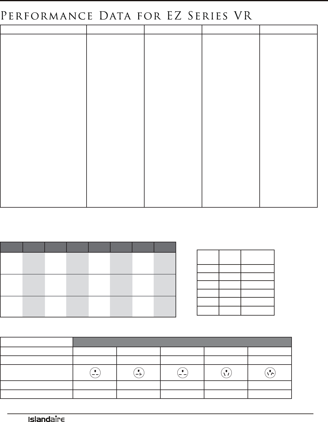
Performance Data for EZ Series VR
EZ09 EZ12 EZ15 EZ18
VOLTS 208-230 265-277 208-230 265-277 208-230 265-277 208-230 265-277
COOLING BTUH 8900 8900 11700 11700 14800 14800 17500 17500
COOLING LATENT BTUH 2225 2225 2925 2925 3700 3700 4375 4375
COOLING SENSIBLE BTUH 6675 6675 8775 8775 11100 11100 13125 13125
AMPS 3.87 3.21 5.09 4.22 6.43 5.34 7.61 6.32
COOLING WATTS 890 890 1170 1170 1480 1480 1750 1750
EER 10 10 10 10 10 10 10 10
CFM HIGH SP 0.1” 424 424 482 482 532 532 565 565
CFM LOW SP 0.1” 370 370 421 421 475 475 525 525
CONDITIONED MAKE UP AIR (CFM)
55 55 55 55 55 55 55 55
HEATING BTUH 8400 8400 10900 10900 13400 13400 15500 15500
HEATING WATTS 820 820 1065 1065 1309 1309 1514 1514
COP 3 3 3 3 3 3 3 3
DEHUMIDIFIER 250W HEATER AMPS (OPT) 1.09 0.90 1.09 0.90 1.09 0.90 1.09 0.90
DEHUMIDIFIER 400W HEATER AMPS (OPT) 1.74 1.44 1.74 1.44 1.74 1.44 1.74 1.44
DEHUMIDIFIER AMPS 1.13 0.90 1.13 0.90 1.13 0.90 1.13 0.90
DEHUMIDIFIER WATTS 260 207 260 207 260 207 260 207
DEHUMIDIFIER LITERS/DAY* 7.90 7.90 7.90 7.90 7.90 7.90 7.90 7.90
DEHUMIDIFIER CFM 55 55 55 55 55 55 55 55
DEHUMIDIFIER CONTROL Automatic Automatic Automatic Automatic Automatic Automatic Automatic Automatic
Heating capacities specied in accordance with ANSI/AHRI standard 390 at conditions of 47 °F DB/43 °F WB outdoor and 70 °F DB/60 °F WB indoor. Wattage, Amperage, COP, EER listings include compressor,
evaporator motor and condenser fan motor. Cooling capacities specied in accordance with ANSI/AHRI standard 390 at conditions of 95 °F DB/75 °F WB outdoor and 80 °F DB/67 °F WB indoor.
*AHAM condition 60% RH, 80 °F DB
HEATING OPTIONS
Heating
Option
Voltage (1) Wattage B.T.U.s (2) Amps (3) MCA (4) MOP (Amps) Power Cord
B
208
230
277
2,050
2,500
2,500
7,000
8,535
8,535
10.46
11.47
9.63
13.1
14.3
12.0
15
15
15
6-15
6-15
7-20
C
208
230
277
2,950
3,600
3,600
10,070
12,290
12,290
14.78
16.25
13.60
18.5
20.3
17.0
20
20
20
6-20
6-20
7-20
E
208
230
277
4,100
5,000
5,000
14,000
17,070
17,070
20.31
22.34
18.65
25.4
27.9
23.3
30
30
30
6-30
6-30
7-30
(1) Voltage is 60Hz, Single Phase, Alternating Current and R.M.S. (2) Heating Capacity (B.T.U./Hr.) based on indoor
blower motor and heating elements. (3) Amp values are a combination of indoor blower motor and heating elements.
ELECTRICAL
EZVR
LINE VOLTAGE 208/230 208/230 208/230 277 277
MAXIMUM AMPERAGE 12 16 24 16 24
WALL SOCKET CONFIGURATION
RECEPTACLE NUMBER NEMA 6-15R NEMA 6-20R NEMA 6-30R NEMA 7-20R NEMA 7-30R
ELECTRICAL HEAT OPTIONS 2.5 2.5 - 3.6 4.2 - 5.0 2.5 - 4.2 2.5 - 4.2
Dehumidifier
Capabilities
Outdoor
% RH
Outdoor
Temp (F)
H2O Removal
(L/Day)
60
80
7.9
60
90
7.8
62
84
9.6
70
81
11.18
85
90
14.4
82
82
17.02

Manufacturer of Quality Air Conditioning and Heating Products • www.islandaire.com • sales@islandaire.com • (800)-886-2759
12
Product Information
e Dr. VTAC system is an add on system to our standard VTAC unit to provide conditioned make up air into
a space through the VTAC unit by providing up to 75 CFM of outdoor air 24/7 by forced fan and cycling dehu-
midier compressor based on outdoor relative humidity levels.
Dr. VTAC was created to solve issues with dehumidication in rooms and to introduce fresh air due to de-
ciencies of oxygen levels. Dr. VTAC is not only a VTAC, it is also a Conditioned Make Up Air unit. New
ASHRAE studies show that many illnesses in hotel rooms can be attributed to an oxygen-decient atmosphere.
Dr. VTAC solves this issue by introducing conditioned make up air that satises both humidity level introduc-
tion and supplied oxygen.
Dr. VTAC is a two-stage system. e primary unit is responsible for control of Sensible Heat that is introduced
into the room via make up air temperature and thermal load of the occupants. e secondary unit is primar-
ily a dehumidication unit that provides up to 75 CFM of outside fresh air into the room. e correction of
the Sensible Temperature comes from the main VTAC system, which provides additional dehumidication
with temperature correction. Overall unit eciency, as compared with standard VTAC’s, is approximately 3%
improvement. e compressor/dehumidication process is controlled by a humidistat (factory set at 50% RH)
that monitors the outdoor relative humidity level and is adjustable by a qualied service person. Below 50%
RH, compressor operation and dehumidication is stopped. However, fan operation continues to provide up
to 75 CFM of outdoor air into the room.
e dehumidication system has a temperature switch that monitors both the refrigeration and the outdoor air
temperatures. If the outdoor air falls below 38 °F, the compressor is disabled with fan operation continuing to
provide outdoor air into the space. All dehumidier controls and safeties are automatically reset. An optional
air tempering heater is available for the fresh air system for applications where operation in cold winter cli-
mates is required. Condensate from the dehumidier drains into the VTAC drain pan, where it is slung onto
the condenser coil for re-evaporation outside when the A/C runs. Excess condensate is drained into the wall
case which can then either drain to the outside through the louver OR be piped to a eld-supplied drainage
system.
ADVANTAGES OF THE DR. VTAC SYSTEM:
1. Lower installation/renovation costs than typical DOAS*
2. Decrease inconvenience to customer due to construction/installation of a DOAS* system
3. Precise humidity control in a room as compared to a simple VTAC vent or power vent system
4. Allows fresh make up air to travel entirely across sleeping and living areas of a room, exiting through a duct
or under the door.
*DOAS = Dedicated Outdoor Air System

Manufacturer of Quality Air Conditioning and Heating Products • www.islandaire.com • sales@islandaire.com • (800)-886-2759
13
Reversing Valve:
e reversing valve controls the direction of refrigerant
ow for both heating and cooling functions and remains
energized as long as the controls are in the heat posi-
tion. When the cooling controls are activated, the valve
automatically reverses to the cooling position.
NOTE: Be sure to connect reversing valve wiring to
the B (blue wire) connection of the thermostat for heat
pump applications.
Heat Pump Features
Heat pump models oer substantial savings over models
with conventional electric resistance heaters.
When the outdoor coil temperature is above 27 °F
(approximately 35 °F outdoor-air temperature), the heat
pump draws heat from outdoor air and uses it to heat
indoor air. Since the heat supplied to the room is the
result of reversing the refrigeration cycle, the heat pump
uses less power than a conventional heating system,
therefore reducing energy costs.
Outdoor ermostat:
During the heating cycle, the outdoor thermostat senses
outdoor coil temperature. If the outdoor coil tempera-
ture falls below 20 °F (approximately 35 °F outdoor-air
temperature), the unit automatically switches to a backup
electric heater. e compressor stops and a blower circu-
lates warm air produced by the heater.
e thermostat automatically switches the unit back to
heat pump operation when the outdoor coil tempera-
ture rises above 40 °F, which is enough to provide heat
to meet demand. e entire operation is completely
automatic.
Product Information (Cont.)
Manufacturer of Quality Air Conditioning and Heating Products • www.islandaire.com • sales@islandaire.com • (800)-886-2759
14
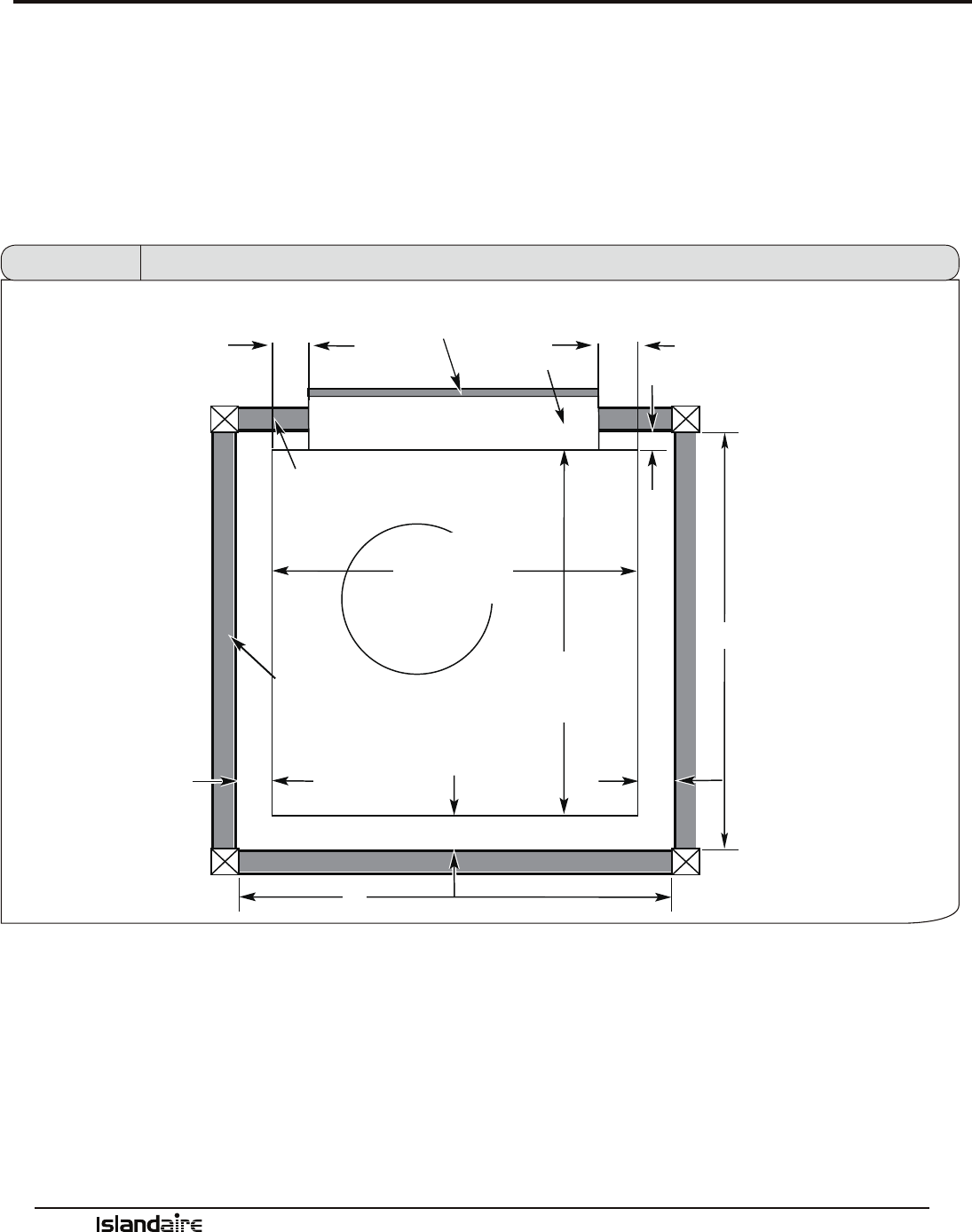
Dimensional Drawings
Units must be installed in accordance with all applicable codes. Ensure that there is adequate clearance for ser-
vicing and proper operation. A minimum clearance of 18 inches in front of the air return is required. Provide
additional space for the service technician to work on the unit. Ensure that drapes, beds, bedspreads, furniture,
etc., DO NOT block either the return or discharge air openings.
Your airow should be balanced based on many factors, such as available ESP, room CFM, and ductwork.
Consult an HVAC engineer for proper applications. Higher CFMs tend to increase sensible capacity, enhance
room circulation and increase duct noise, while lower CFMs tend to increase latent capacity and reduce noise.
Important Notes
‘A’ dimension determined by wall thickness and plenum size selected
‘B’ dimension minimum 4” for front installation,
‘B’ dimension minimum 5” for side installation (7” recommended)
‘C’ and ‘D’ dimensions minimum 3” for front installation
‘C’ and ‘D’ dimensions minimum 3” for side installation
‘E’ dimension minimum for 28” door - 33”
‘E’ dimension minimum for Islandaire Access Panel - 30”
Figure 1 Dimensional Drawings (Unit Top Down View)
2 1/4”
OUTDOOR GRILLE
PLENUM
1”
PLENUM
A
OUTDOOR WALL
23 1/8”
WIDE
VP/VR CHASSIS CASE
23 1/8”
DEEP
E
D
B
C
E
CLOSET WALL
Manufacturer of Quality Air Conditioning and Heating Products • www.islandaire.com • sales@islandaire.com • (800)-886-2759
15
Dimensional Drawings (Cont.)
See page 16
REMOVE HEX
SCREW
REMOVE TOP AND
SIDE SCREWS,
ROTATE OUTWARDS
FULLY
REMOVE
SIDE
PANEL
SCREWS
PULL UNIT FORWARD SLIGHTLY,
THEN SLIDE OUT OF CASE
SIDE-MOUNTED CHASSIS REMOVAL:
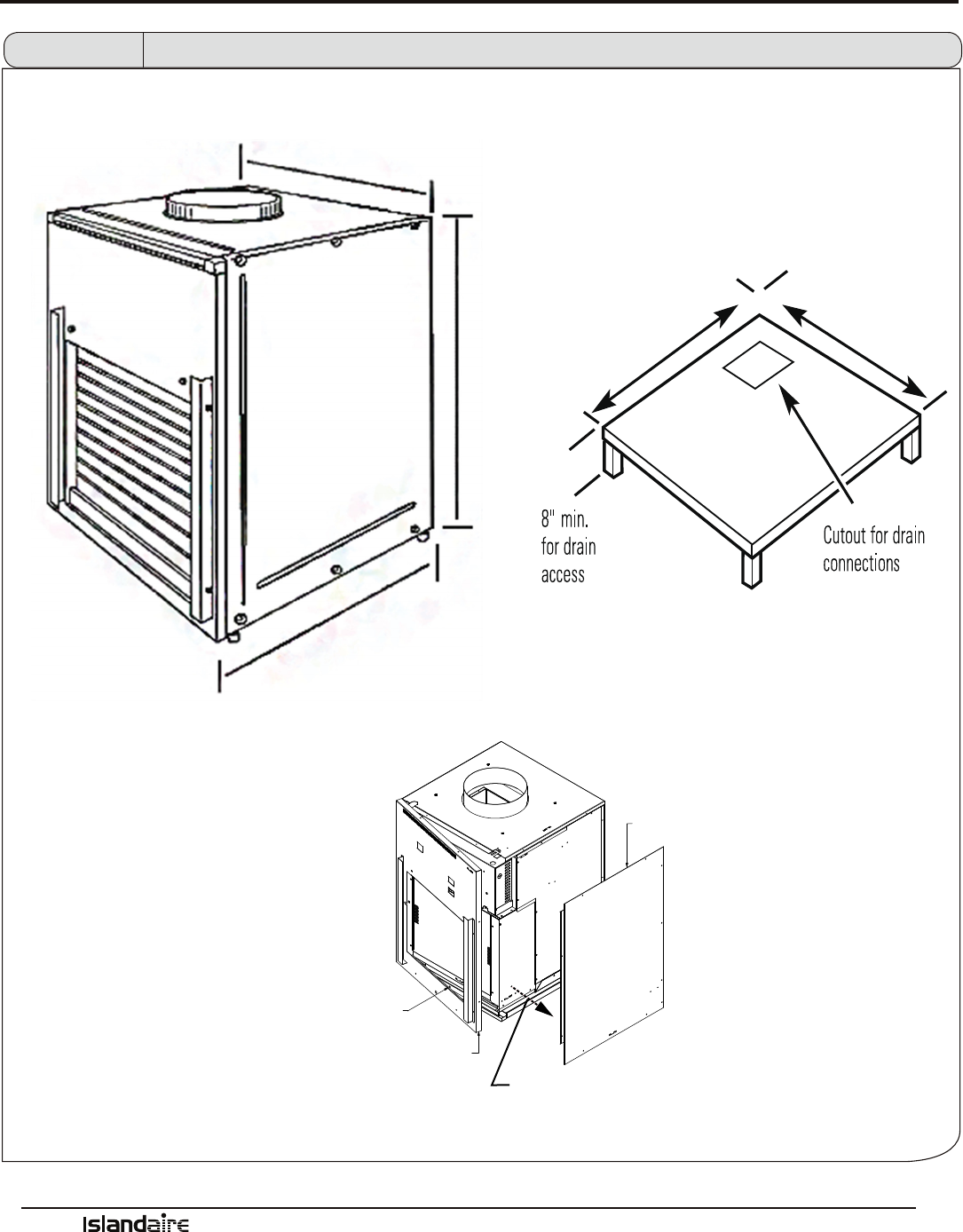
Figure 1-A Dimensional Drawings (Unit and Platform)
23 1/8”
23 1/8”
31”
23 1/4” 23 1/4”
Manufacturer of Quality Air Conditioning and Heating Products • www.islandaire.com • sales@islandaire.com • (800)-886-2759
16
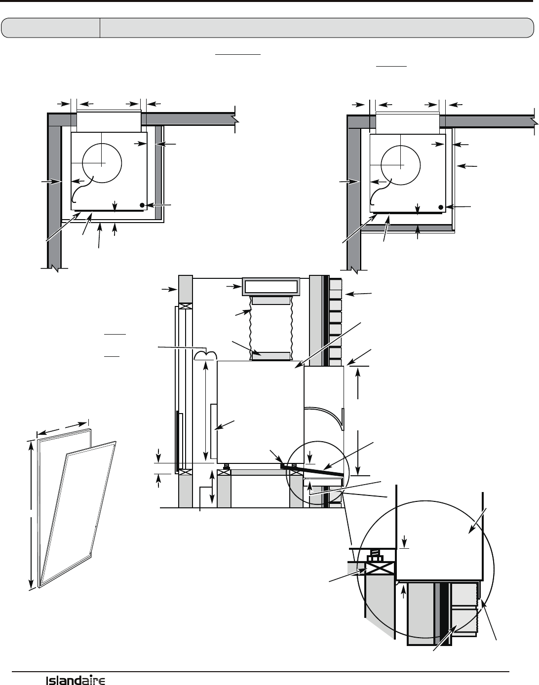
Dimensional Drawings (Cont.)
Side View
UNIT INSTALLED THROUGH FRONT OF
CASE (RECOMMENDED)
UNIT INSTALLED THROUGH
SIDE OF CASE
FILTER
BRACKET
FEMALE DRAIN
FITTING 3/4”
PLENUM CUTOUT
32-1/4”H x 20-1/8”W
INSIDE WALL
OUTSIDE WALL
RIGID
DUCTWORK
FLEXIBLE OR
RIGID DUCT
UNIT/CASE
WALL PLENUM - EXTEND
1/4” FOR CAULKING
EXTERIOR/OUTSIDE
EXTERNAL DRAIN LINE
BOTTOM OF CASE APPROX. 2”
ABOVE BOTTOM OF PLENUM
WALL PLENUM
BOTTOM OF CASE
APPROX. 2” ABOVE
BOTTOM OF PLENUM
PLATFORM
PLATFORM: 23-1/4” x 23-1/4”
SQUARE
MIN. LOAD CAPACITY: 230 LBS.
8” MIN. FOR
DRAIN ACCESS
• 4” MIN. FROM FRONT OF CASE - UNIT
INSTALLED THROUGH FRONT OF CASE
• 5” MIN. FROM FRONT OF CASE - UNIT
INSTALLED THROUGH SIDE OF CASE
• 3” MIN. FROM TWO SIDES OF CASE
OUTSIDE WALL
FIELD SUPPLIED
OUTER FLASHING
A
B
A: MINIMUM RECOMMENDED ACCESS DOOR WIDTH 30”
B: MINIMUM RECOMMENDED ACCESS DOOR HEIGHT 50”
Top View Top View
RTS CONNECTION
REMOVE FRONT
COVER TO GAIN
ACCESS
~2 1/4”
3” MIN.
4” MIN.
UNIT
FRONT
DOOR/ACCESS PANEL
~1”
3” MIN.
10-1/2”
10”
DUCT
11-3/4”
ELECTRICAL
CONNECTION
ARCHITECTURAL LOUVER
19-7/8”
AIR DISCHARGE
OUTLET
2-INCH (MIN.)
10-INCH (MAX.)
~2 1/4”
3” MIN.
3” MIN.
7” RECOMMENDED,
5” MIN.
UNIT
FRONT
DOOR/ACCESS
PANEL
~1”
11-3/4”
10”
DUCT
10-1/2”
ARCHITECTURAL LOUVER
ELECTRICAL
CONNECTION
19-7/8”
RTS CONNECTION
REMOVE FRONT COVER
TO GAIN ACCESS
Figure 1-C Dimensional Drawings (Chassis)
Manufacturer of Quality Air Conditioning and Heating Products • www.islandaire.com • sales@islandaire.com • (800)-886-2759
17
Installation Instructions - Wall Plenum
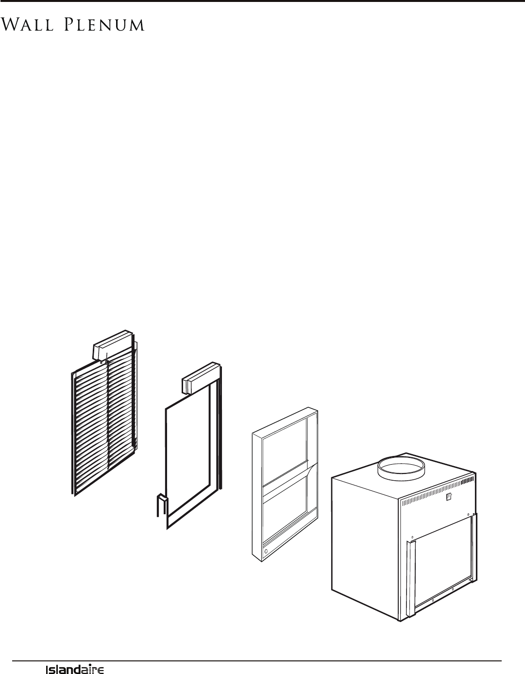
Wall Plenum
Since the VTAC unit itself does not install in the wall opening, the use of a wall plenum is necessary to contain
and separate the outdoor air paths to prevent the discharge air from being drawn back into the unit. e ple-
num must be able to hold water in the bottom without leaking into the wall cavity. e installation of ashing,
with a 45° drip-lip, is recommended below the plenum.
e plenum is not load bearing, so a proper header needs to be installed above the plenum just as over any
window opening in the wall. If the building construction is brick, concrete block, or other non self-supporting
material, a lintel must be installed over the plenum opening. e plenum is to be installed square and level
in the opening and secured to the wall construction with screws or nails in the sides located a minimum of 2”
from the bottom of the plenum. No nails or screws may be used in the bottom or top of the plenum to ensure
against water entering the wall cavity. e plenum must be caulked (on all four sides) along the outdoor wall
face and along the interior wall to prevent air inltration and water intrusion.
e wall opening location for the plenum must extend 1” below the top of the Installation Platform. Since the
platform must be a minimum of 8” o the oor, the cutout for the plenum must be a minimum of 7” plus the
thickness of the platform base, o the interior nished oor.
Islandaire oers ve plenums; the choice of the correct plenum is determined by the thickness of the building’s
exterior wall (see below). Each plenum is 19 7/8” wide by 32” high and requires a 20 1/8” wide by 32 1/4” high
cutout in the wall.
Prepare the closet ductwork for later connection to the case. Plenum duct should be insulated to prevent con-
densation and to reduce air noise.
PROPERLY LEVEL AND
SQUARE PLATFORM
ARCHITECTURAL LOUVER
EXTERIOR/OUTSIDE WALL
WALL PLENUM
CASE
Type 1: 6”D x 19 7/8”W x 32”H
Type 2: 8”D x 19 7/8”W x 32”H
Type 3: 10”D x 19 7/8”W x 32”H
Type 4: 12”D x 19 7/8”W x 32”H
Type 5: 15”D x 19 7/8”W x 32”H
Manufacturer of Quality Air Conditioning and Heating Products • www.islandaire.com • sales@islandaire.com • (800)-886-2759
18
Installation Instructions - Exterior Grille
Standard exterior
(Rear) Grille
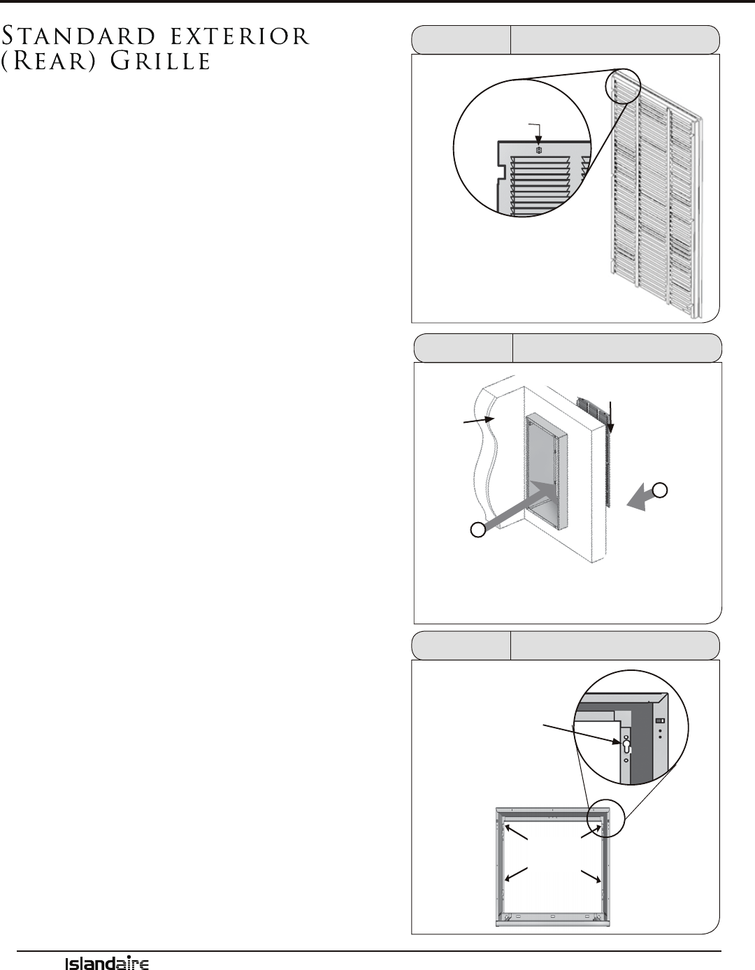
e standard exterior grille (louver) is mounted to the
exterior ange of the plenum and held in place with four
screws inserted from inside the enclosure closet. e
grille is designed specically for use with the VTAC unit
and the use of any other grille must be approved by Islan-
daire Air Conditioning Applications Engineering.
1. Prepare the grille for installation by installing the ve
plastic fasteners supplied through the holes in the
grille.
2. Guide the alignment pins, located on the lower right
and lower le hand corners of the grille into their
corresponding holes on the rear outside edge of the
plenum.
3. If installing the grille from inside the room, use a plas-
tic wire zip-tie or tie a short length of string or insu-
lated wire around several louvers as a holding device
in order to keep a rm grasp on the grille. Angle the
grille through the opening at the rear of the plenum,
then pull the grille back to the plenum and align the
screw heads to the hole. Be sure to keep a rm grip
on the grille to prevent it from dropping and/or caus-
ing possible injury and/or property damage.
4. Secure the grille to the plenum by installing screws
into the plastic fasteners. Be careful not to damage
fasteners by overtightening. Remove the holding
device (plastic wire zip-tie, etc.) when installation is
complete.
PLASTIC
FASTENER
Figure 2 Standard Grille Fastener
INSIDE
WALL
Figure 3 Standard Grille Installation
STANDARD
GRILLE
ANGLE THE GRILLE
THROUGH THE OPENING
AT BACK OF PLENUM
PULL FORWARD
TO INSERT SCREW
HEADS INTO
KEYHOLE SLOTS
HOLES
SECURE THE GRILLE TO THE
PLENUM BY TIGHTENING
SCREW HEADS IN HOLES.
DO NOT OVERTIGHTEN
Figure 4 Standard Grille Installation
Manufacturer of Quality Air Conditioning and Heating Products • www.islandaire.com • sales@islandaire.com • (800)-886-2759
19
Installation Instructions - Exterior Grille
Architectural
Exterior (Rear) Grille
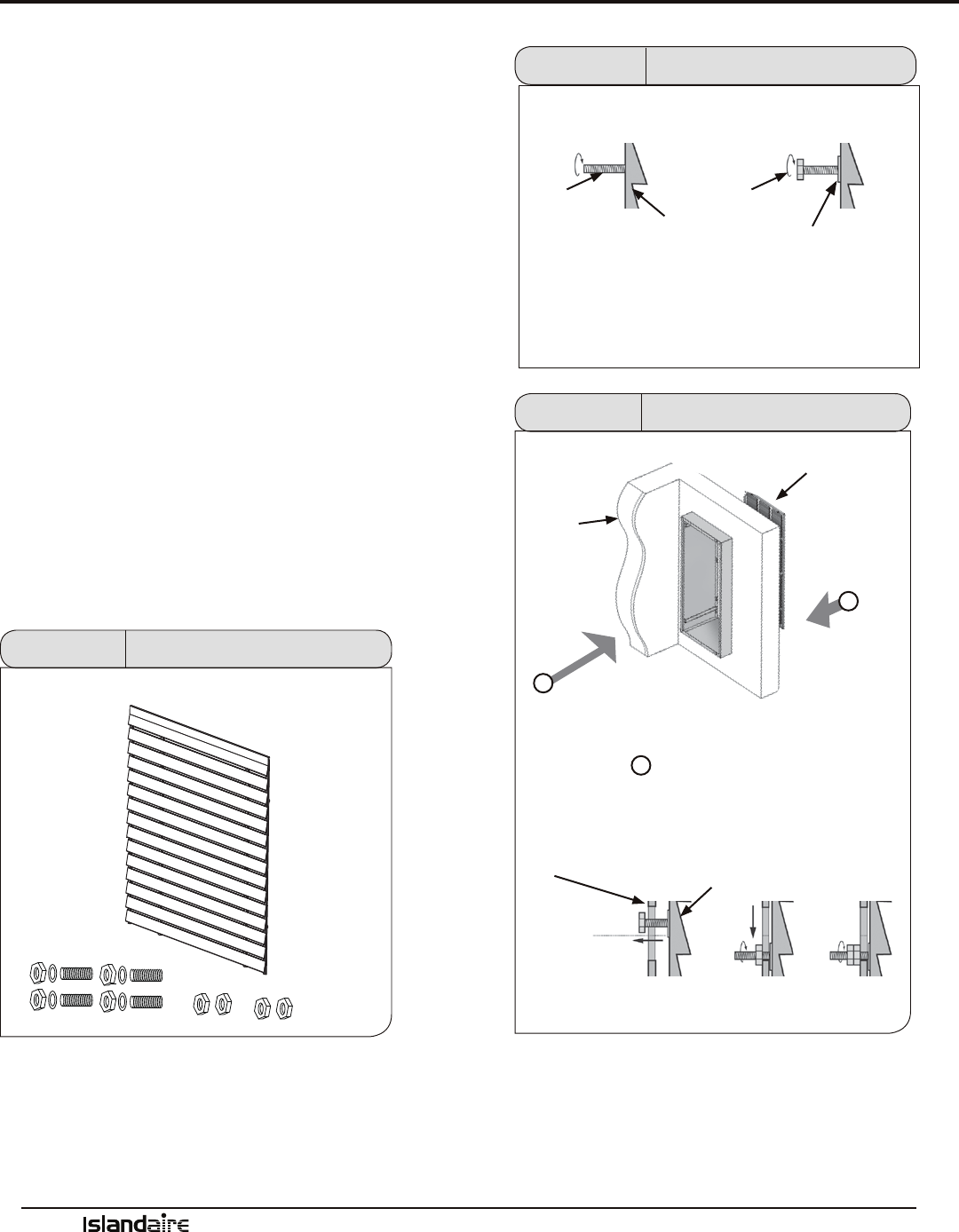
e architectural rear grille directs condenser airow
and provides a protective barrier for the outdoor coil.
Either the approved Standard or Architectural grille must
be installed before installing the chassis.
1. Install the four threaded studs into the threaded
openings on the inside face of the grille. Install a
washer and one hex nut to the end of each stud.
2. Manipulate the grille out through the rear ple-
num opening. Be sure to keep a rm grip on the
grille to prevent it from dropping and/or causing
possible injury or property damage.
3. Attach the grille to the plenum by aligning and
inserting the hex nut threaded onto the studs
through the holes in the plenum.
4. Secure the grille to the plenum by tightening the
hex nut and adding and tightening an additional
hex nut.
Architectural Rear Grille, 4 Studs, 4 Washers,
(8) Hex Nuts
Figure 5 Architectural Rear Grille Parts
STUD
HEX NUT
WASHER
INSTALL THE FOUR THREADED STUDS INTO THE THREADED
OPENINGS ON THE INSIDE FACE OF THE GRILLE. INSTALL
WASHERS AND HEX NUTS TO THE END OF EACH STUD.
Figure 6 Threaded Stud Installation
ARCHITECTURAL-
GRILLE
INSIDE
WALL
ANGLE THE GRILLE THROUGH
THE OPENING AT BACK OF
PLENUM
PLENUM
ARCHITECTURAL
GRILLE
PULL FORWARD TO GUIDE HEX NUTS
THROUGH HOLES IN PLENUM, THEN
TIGHTEN HEX NUTS. SECURE WITH AN
ADDITIONAL HEX NUT.
Figure 7 Arch. Rear Grille Installation
1
2
2
ARCHITECTURAL
GRILLE
Manufacturer of Quality Air Conditioning and Heating Products • www.islandaire.com • sales@islandaire.com • (800)-886-2759
20
Installation Instructions - Base Platform
Base Platform Construction
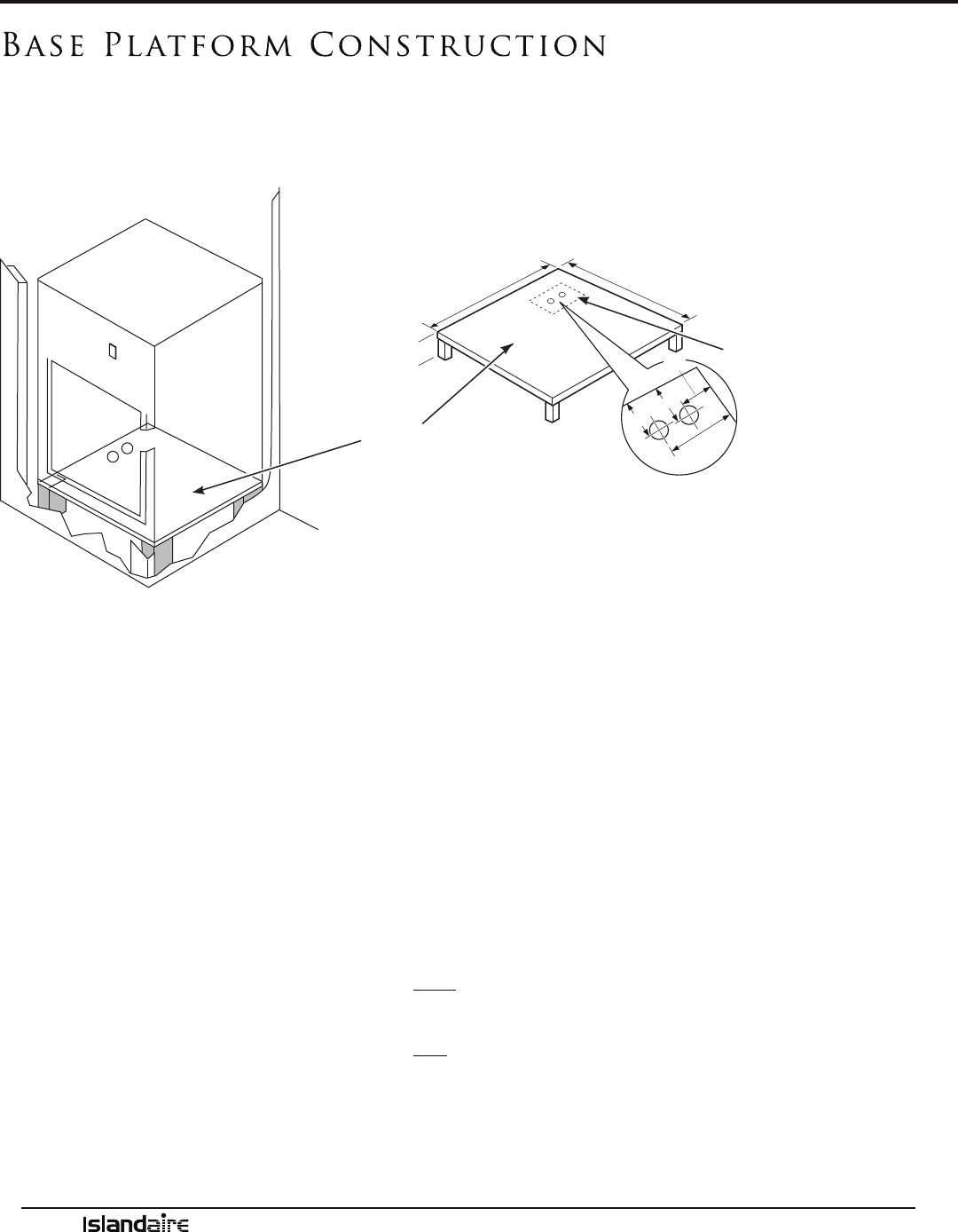
e VTAC unit requires a eld-supplied base platform (having a load-bearing capacity of 230 lbs. mini-
mum). For warranty purposes, the base platform must be constructed to ensure the unit chassis can be
removed through the access panel. Proceed as follows:
1. Construct a 23 1/4” min. x 23 1/4” min. square platform with legs to raise platform a minimum of 8”
(12” recommended), see diagram above.
2. Make the drain hole cutout(s) as follows
• Primary Drain - Centerline of drain is approximately 4.695” from le platform edge and 8.875”
from back platform edge.
• Secondary Drain - Centerline of drain is approximately 6.625” from le platform edge and 5.625”
from back platform edge.
3. Place the platform in the utility closet large enough to provide the following clearances between it and
the interior surface of the walls/door/panel:
NOTE: When determining the closet depth, consideration must be given to the fact that the ple-
num will protrude into the closet because the plenum will be thicker than the exterior wall.
• If VTAC unit is to be installed through the front of case: 4” minimum clearance from the front of
the platform to inside of the closet door, 3” minimum clearance from each side of the case.
• If VTAC unit is to be installed through the side of case: 5” minimum clearance from the front of the
case, 5” minimum clearance from each side.
4. e platform legs must be positioned so access to the unit drain connections are not blocked. Align
the platform with the opening of the wall plenum and secure to the oor using appropriate brackets
and screws.
PLATFORM
6.0
6.2
4.62
8.7
LEFT SIDE OF PLATFORM
23.25” MIN
8” MIN FOR
DRAIN ACCESS
BACK SIDE OF PLATFORM
23.25” MIN
CUTOUT FOR DRAIN
CONNECTION(S) (SEE
NOTE BELOW)
NOTE: Specic cutout size and locations for drain con-
nections must be conrmed by the installer for the given
installation.
Manufacturer of Quality Air Conditioning and Heating Products • www.islandaire.com • sales@islandaire.com • (800)-886-2759
21
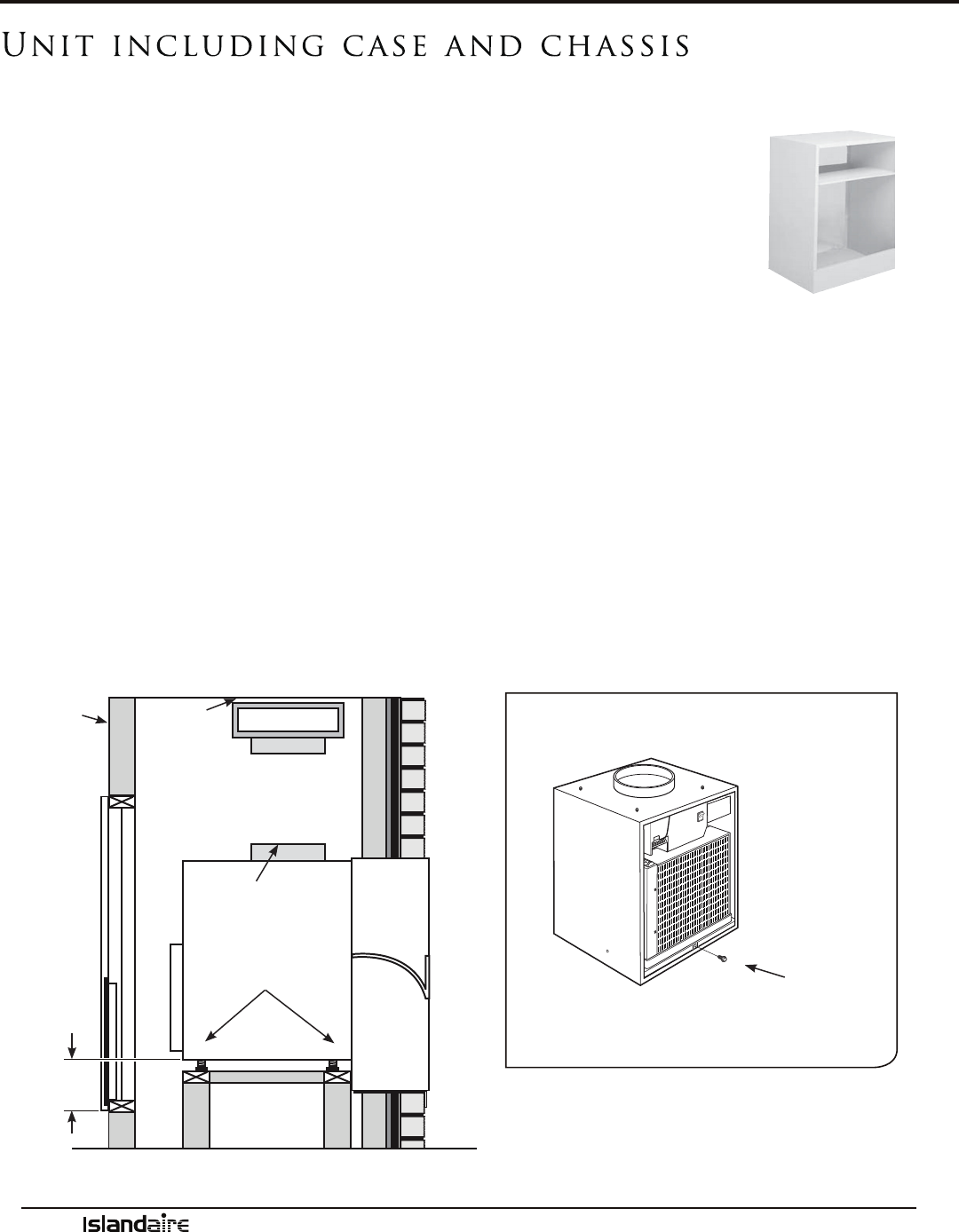
Unit including case and chassis
e VTAC unit is packaged with the case and the front panel in place (lter not included).
1. Remove the front case panel and pull the unit chassis out of the case. Remove
the side panel if a side installation is to be made.
2. Place the empty case onto the base platform in the closet with the outdoor side
facing the wall plenum and slide unit up to plenum.
3. Level the case side-to-side and front-to-back using the four leveling legs.
4. Using the holes in the bottom of the case as guides, drill holes in the mounting
platform. Use four eld-supplied bolts, washers and nuts to secure the case to the platform. Do not
tighten the bolts to the point of distorting the case. Failure to properly secure the case to the platform
may result in excessive unit vibration and increased noise level.
5. Align the case with the plenum opening and attach using six eld-supplied sheet metal screws (stain-
less screws recommended).
6. Slide the unit chassis into the case, either through the front or side panel opening. Push the unit all of
the way into the case until it stops.
NOTE: Either of the case sides may be removed to enable the unit to be slid into the case.
7. With the chassis in position in the case, replace the side panel (if removed).
8. Ground the unit to the case by installing the front case-to-unit hex bolt.
CASE
INSIDE WALL
RIGID
DUCTWORK
AIR DISCHARGE
OUTLET
LEVELING LEGS
2-INCH (MIN.)
10-INCH (MAX.)
HEX BOLT
Installation Instructions - Case & Chassis
Manufacturer of Quality Air Conditioning and Heating Products • www.islandaire.com • sales@islandaire.com • (800)-886-2759
22
Installation Instructions - Drains
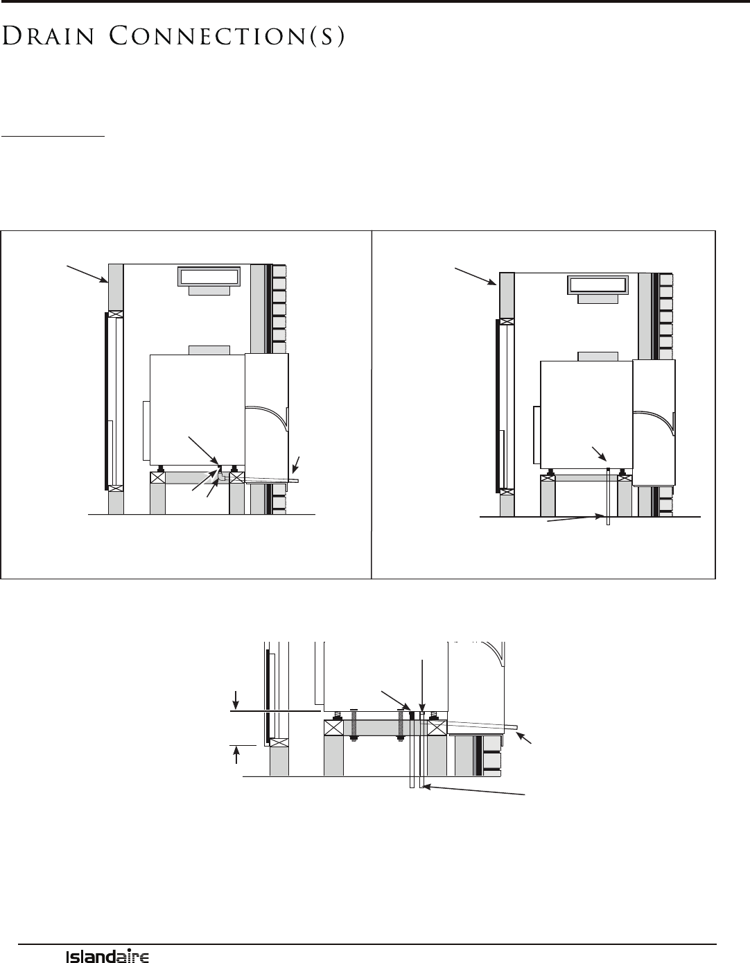
Drain Connection(s)
e VTAC unit is equipped with two drain ttings (primary and secondary drains). An external or an
internal drain must be attached to the primary drain connector. e secondary drain is provided for con-
nection when required by state and local codes. Refer to local codes for proper installation of the drains.
External Drain:
Attach a 90° PVC elbow to the unit’s female 3/4” NPT drain connector. Use the other end of the elbow to
run a 3/4” schedule 40 PVC pipe through the knockout hole of the wall plenum to the outside. A notch
must be cut in the rear grille (louver blade) to allow tube to pass through. Seal the gap between the wall
plenum hole and PVC tube.
* Ensure drain lines going out the plenum are sloped downward to allow water to drain out.
e secondary drain hole is shipped open (unplugged) and must either be plugged if not used or con-
nected to an independent drain system. If a secondary drain system is used, attach a 90° schedule 40
PVC elbow to the secondary drain hole directed toward the secondary drain system. If a secondary drain
system is NOT used, install a 3/4” schedule 40 PVC plug to cap the hole. If the secondary drain is not
used, seal its drain port with a 3/4” MNPT plug.
PVC
90° ELBOW
PVC
(EXTERNAL
DRAIN)*
INSIDE WALL
FEMALE DRAIN
FITTING 3/4”
Side View
Primary Drain (External)
Side View
INSIDE WALL
PVC
(INTERNAL DRAIN)
FEMALE DRAIN
FITTING 3/4”
Primary Drain (Internal)
SECONDARY 3/4” DRAIN
OPTION. IF NOT USED,
SEAL WITH A MNPT PLUG.
PRIMARY FEMALE
DRAIN FITTING
3/4”
NOTE: PIPING IS NOT
SUPPLIED WITH THE UNIT.
OBTAIN LOCALLY.
EXTERNAL
DRAIN OR
INTERNAL
DRAIN(S)
2-INCH (MIN.)
10-INCH (MAX.)
Manufacturer of Quality Air Conditioning and Heating Products • www.islandaire.com • sales@islandaire.com • (800)-886-2759
23
Installation Instructions (Power Cord, Duct)
Unit Power Connection
1. 230/208V units are equipped with LCDI or AFCI
power cords and can open the electrical circuit to
the unit. In the event the unit does not operate,
check the reset button located on or near the head
of the power cord as part of the normal trouble-
shooting procedure. Make power connections to
the unit (refer to WIRING DIAGRAMS section).
2. Once the unit is properly wired, measure the unit
supply voltage. Voltage must fall within the voltage
utilization range as shown in the table below.
VOLTAGE MEASUREMENTS
OPERATING VOLTAGE
UNIT VOLTAGE RATING
VOLTAGE UTILIZATION RANGE
MINIMUM MAXIMUM
230/208 197 253
265 238 292
Figure 8 LCDI Cord
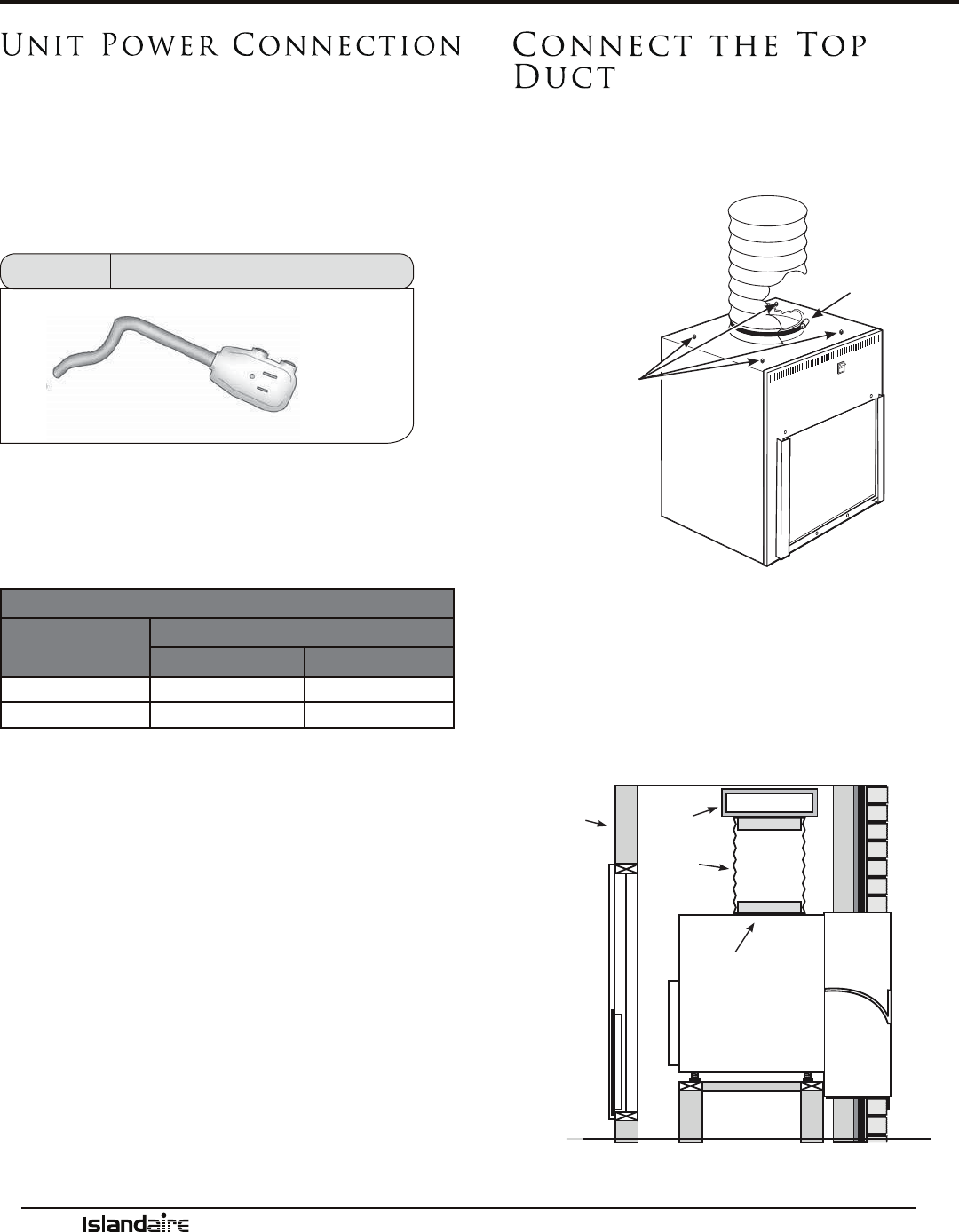
Connect the Top
Duct
1. Seal the case top duct to the VTAC unit chassis
by turning the four case top duct adjusting screws
until they are tight.
2. A 10” diameter ange on the air discharge outlet
is used to connect to eld supplied, insulated,
exible or rigid transition duct with an adjustable
ring clamp. Flexible duct may be used for transi-
tions only, rigid duct must be used for 90° bends
and tees. Do not use exible duct for unsup-
ported runs of ve feet or more. Extra exible
duct slack can greatly increase static pressure.
FLEXIBLE
OR RIGID
DUCTWORK
CLAMP
CASE TOP
DUCT ADJUST-
ING SCREWS
AIR DISCHARGE
OUTLET
INSIDE
WALL
RIGID DUCT-
WORK
FLEXIBLE
OR RIGID
DUCTWORK
Manufacturer of Quality Air Conditioning and Heating Products • www.islandaire.com • sales@islandaire.com • (800)-886-2759
24
THERMOSTAT
MAXIMUM WIRING
LENGTH FOR THERMOSTAT
CONNECTION TO UNIT:
66 FT. FOR 18 AWG
60 FT. FOR 20 AWG
(AWG - AMERICAN WIRE GAUGE)
UNIT CONNECTIONS
Wireless Wall
Mounted Thermostat
Wireless wall thermostats are designed to provide
precise thermostat control without the installation
labor and expense of wiring.
• Powered by AA batteries
• Mounts in any suitable location that will pro-
vide an accurate room temperature reading.
• Large LCD display provides the user with
current room temperature, set point tempera-
ture, time, program interval, and other system
status information.
Remote Control Node
Used with a wireless wall thermostat, the RCN com-
municates with the thermostat using unlicensed 900
MHz, radio frequency range.
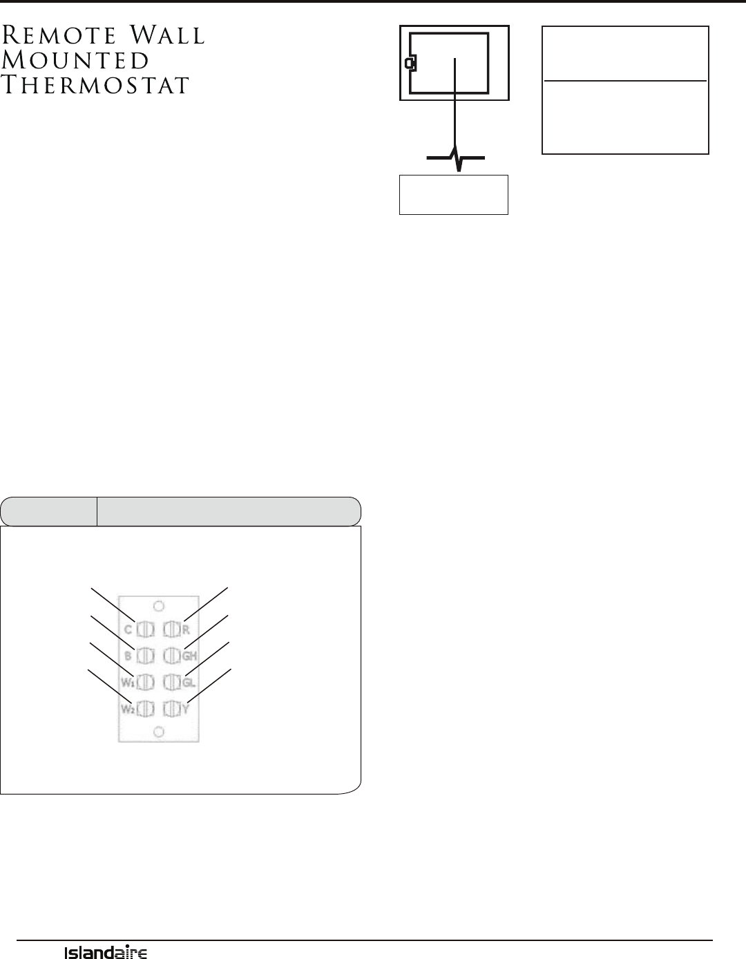
Remote Wall
Mounted
Thermostat
e VTAC unit can be controlled by any remote
electronic thermostat that can interface with RCB-
WYG terminals. In terms of outputs, there are two
types of thermostats: mechanical and solid-state.
Refer to the manual provided with the thermostat
for proper connections and settings.
A Remote ermostat Terminal Block is available,
and is located on top of the control box, behind the
front panel of the case. It provides a connection
for a remote thermostat and energy management
inputs.
NOTE: Ensure power to the unit is shut o prior to
making any electrical connections.
1. Connect the thermostat wires to the unit. You
can wire any type of 24 VAC thermostat straight
into the Remote ermostat Terminal Block.
Figure 9
Thermostat Terminal Block
R
GH
Y
GL
C
B
W2
W1
Installation Instructions - Thermostat

Manufacturer of Quality Air Conditioning and Heating Products • www.islandaire.com • sales@islandaire.com • (800)-886-2759
25
Terminal W1 (White)
When this low voltage terminal is connected to
the R terminal, and the unit is in the remote mode,
rst hydronic heat is attempted, and electric heat
is switched on as backup (the GL and GH terminal
must also be connected to the R terminal). is is
subject to the congured heat modes available.
Terminal GL (Orange)
When this low voltage terminal is connected to
the R terminal, and the unit is in remote mode, the
blower/fan will be requested for operation on low
speed.
Terminal C(Black)
Low voltage terminal, 24 VAC common, to provide
opposite polarity voltage to wall thermostat.
Terminal R (Red)
Low voltage terminal to supply voltage to an exter-
nal wall-mounted thermostat. is terminal is
capable of supplying 100 mA at 18-30 VAC RMS
over the entire input voltage range specied.
Terminal GH (Green)
When this low voltage terminal is connected to
the R terminal and the unit is in remote mode, the
blower/fan will be requested for operation on high
speed.
Terminal B (Blue)
When this low voltage terminal is connected to the
R terminal and the unit is in the remote mode, the
reversing valve is energized. Hydronic and electric
heat shall be attempted as backups if the B terminal
is asserted and the compressor is locked out or dis-
abled. is is subject to the congured heat modes
available.
Terminal Y (Yellow)
When this low voltage terminal is connected to
the R terminal, and the unit is in remote mode, the
compressor will be switched on (the GL or GH ter-
minal must also be connected to the R terminal).
Remote Thermostat Interface
During a call, the remote thermostat will pass R back to the controller on a respective terminal. See
below for descriptions of each terminal.
Installation Instructions - Thermostat
(Cont.)
Manufacturer of Quality Air Conditioning and Heating Products • www.islandaire.com • sales@islandaire.com • (800)-886-2759
26
Installation Instructions - Interior Grille
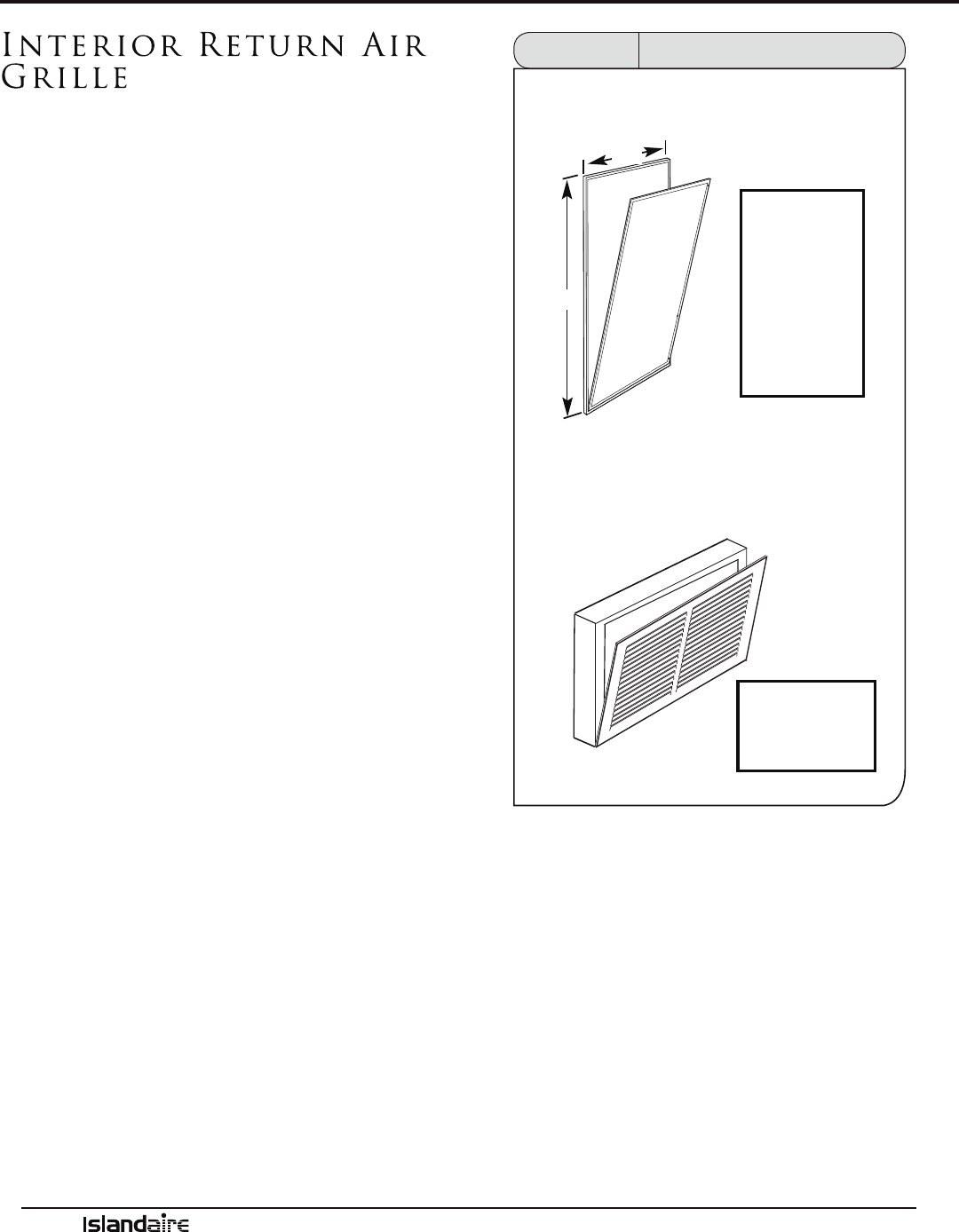
Interior Return Air
Grille
e return air from the room to the VTAC unit
enters the enclosure closet using a return air grille
(see gure 10). A wall-mounted, front access panel
(item 1) in combination with a wall-mounted,
return air grille (item 2) is required.
1. e front access panel requires a 28” wide by 48”
high cutout in the door.
2. e return air grille (item 2) is designed to be
installed in a 20” wide by 20” high cutout in
the wall. An air lter can t into the bracket in
the rear of the return air grille or in the bracket
located on the front panel of the VTAC unit.
3. A sound-reduction louvered panel that mounts in
the door is also available. e sound-reduction
panel requires a 28” wide by 48” high cutout in
the door. e air lter would be installed in the
lter bracket located on the front panel of the
VTAC unit.
Figure 10 Interior Grille Installation
50”
ITEM 1: The front access panel - must be lined up with
the cutout on the VTAC unit case
ITEM 2: Return Air Grille
CUTOUT
DIMENSIONS
28”W x 48”H
30”
CUTOUT
DIMENSIONS
20”W x 20”H (min.)
Manufacturer of Quality Air Conditioning and Heating Products • www.islandaire.com • sales@islandaire.com • (800)-886-2759
27
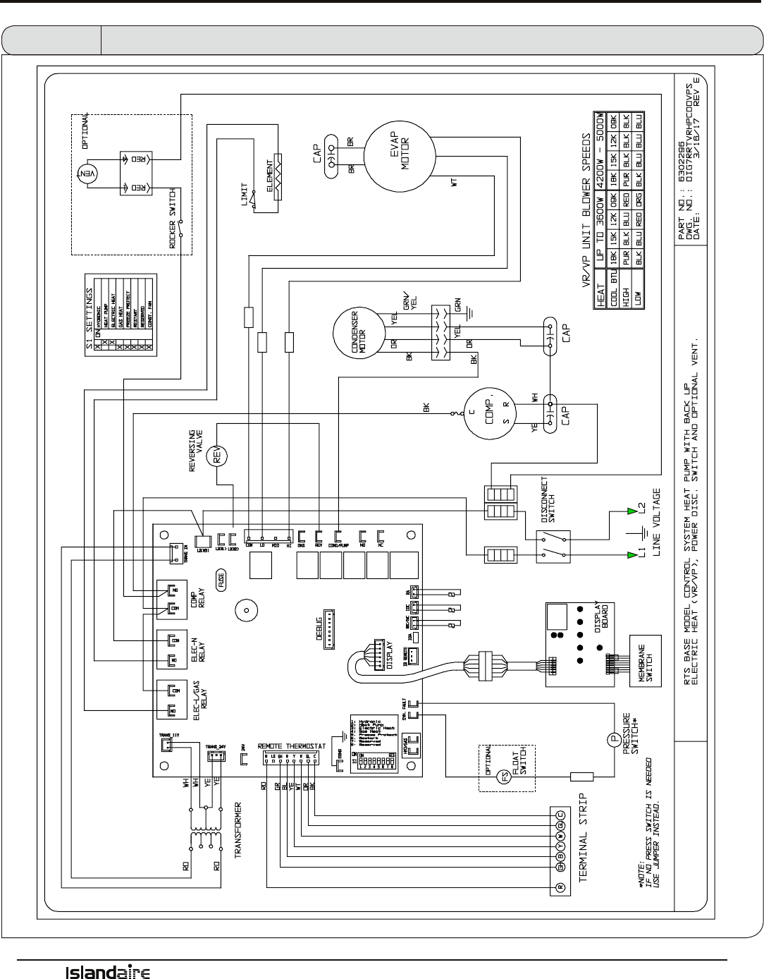
Wiring Diagrams
Figure 11 Wiring Diagram - EZ VP Series VTAC Unit
*NOTE: ABOVE DIAGRAM IS TYPICAL. FOR UNIT SPECIFIC WIRING, REFER TO DIAGRAM PROVIDED WITH UNIT (ENCLOSED IN VINYL POUCH)
Manufacturer of Quality Air Conditioning and Heating Products • www.islandaire.com • sales@islandaire.com • (800)-886-2759
28
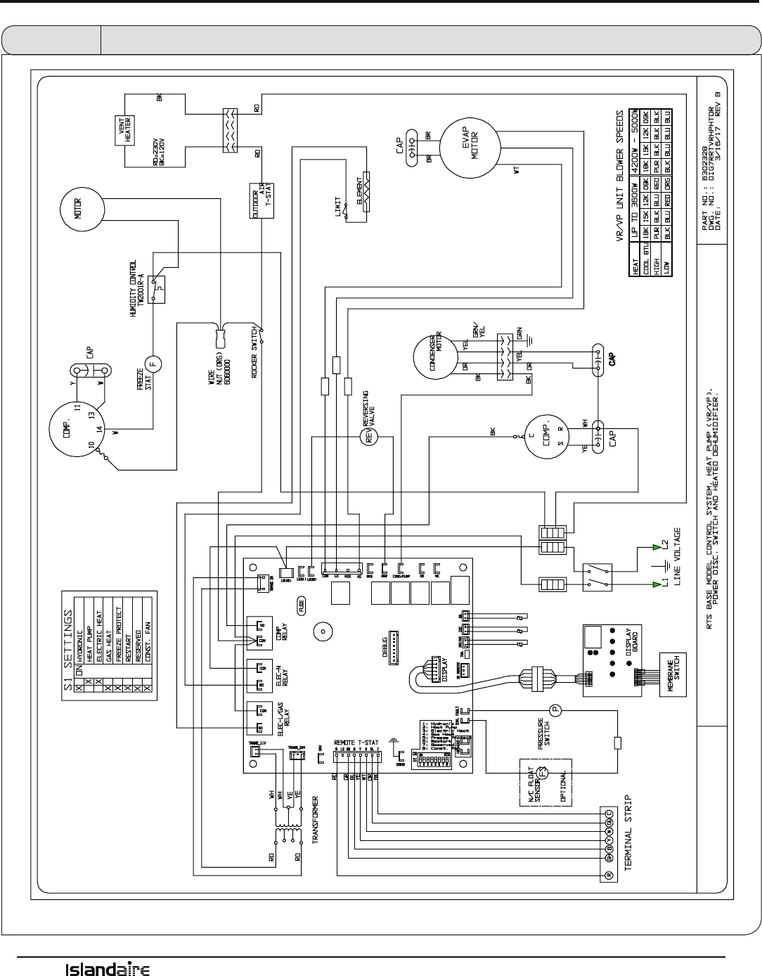
Wiring Diagrams (Cont.)
Figure 12 Wiring Diagram - EZ VR Series VTAC Unit
*NOTE: ABOVE DIAGRAM IS TYPICAL. FOR UNIT SPECIFIC WIRING, REFER TO DIAGRAM PROVIDED WITH UNIT (ENCLOSED IN VINYL POUCH)
Manufacturer of Quality Air Conditioning and Heating Products • www.islandaire.com • sales@islandaire.com • (800)-886-2759
29
System Controls and Management
USER INTERFACES
e Islandaire EZVP VTAC can be operated using several dierent control systems. Described below are some of
the important control features and a brief description of their functions.
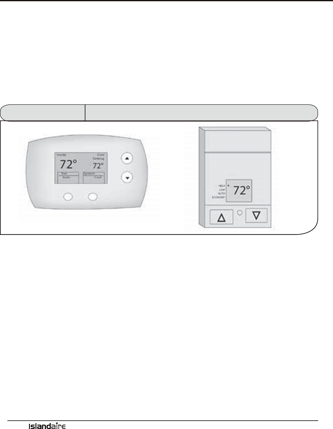
Wall Thermostats
Terminal connections on the main control board allow easy conversion from an on-board control panel to a wall-
mounted thermostat control (wired or wireless).
See page 24 & 25 for full details
Front Desk Control
Low voltage terminals on the main control board allow easy connection to a front desk energy management
system. Front desk controls allow the unit to be operated from a remote location. Front desk controls can reduce
energy consumption by allowing front desk personnel to turn the unit o when a room is vacant.
Figure 13
Wall Thermostats

Manufacturer of Quality Air Conditioning and Heating Products • www.islandaire.com • sales@islandaire.com • (800)-886-2759
30
System Controls and Management (Cont.)
Diagnostic Software
e smart logic control performs self-diagnostic tests
that inform service personnel about possible problems.
Error codes are continuously displayed during trouble-
shooting and maintenance until the problem has been
resolved.
Custom Operation
and Continual
Room Temperature
Monitoring
e smart logic control utilizes a built-in sensor for mea-
suring room temperature. When a
pre-determined (user-dened) set point is reached, smart
logic controls automatically adjusts the unit operation to
maintain the room temperature.
Controls Logic
e Islandaire VTAC unit is equipped with an electronic system that runs smart control logic with associated sen-
sors. Built-in safety features protect the unit from the damaging eects of freezing temperatures and power inter-
ruptions. Energy management functionality allows the unit performance to be customized to control its power
consumption. Displaying fault codes help personnel quickly correct any problems if they occur.
Listed below are the built-in automatic features and a brief description of their functions. See Performance Speci-
cations section starting on page 33 for full details of all functions.
Room Freeze
Prevention
e indoor freeze protection monitoring system prevents
unoccupied rooms from reaching freezing levels that can
damage plumbing and xtures. is feature is automatic
regardless of mode and does not require any additional
settings. is feature can be turned on or o by adjusting
DIP switch settings on the main control board.
High Temperature
Compressor
Protection
e life of the compressor is extended through built-in
temperature protection. e system will initiate a com-
pressor lockout if the compressor temperature exceeds
154 °F or if the outdoor air temperature falls below 35 °F.
Low Temperature
Compressor
Protection
An indoor frost sensor will disable the operation of the
compressor if freezing conditions exist. is protects
the compressor from damage due to airow reduction
or low outdoor air temperature. When the coil tempera-
ture rises to a safe temperature the compressor resumes
normal operation.
Manufacturer of Quality Air Conditioning and Heating Products • www.islandaire.com • sales@islandaire.com • (800)-886-2759
31
OPERATING GUIDELINES
• Do not block airow. Ecient operation of the
unit depends on free circulation of air. Paper,
leaves, and other debris can reduce eciency and
cause serious damage to the compressor.
• Ensure that objects such as drapes, furniture, or
plants are not blocking the supply and return
airow.
• Do NOT operate unit with front panel removed or
without lter, as this will void any warranties.
• Keep doors and windows closed. Leaving them
open will increase the workload on the unit and
will result in higher operating cost and excessive
condensate.
Do NOT operate the unit while the building is still
under construction or restoration. Construction dust
can clog the lter and cause permanent damage to other
components.
Freeze Protection Feature
If the temperature in a vacant room falls
below 50°F the freeze prevention thermo-
stat automatically starts the heating cycle to
prevent freezing conditions. All other opera-
tions will be disabled until the temperature
rises above 58°F. When the temperature of the
freeze prevention thermostat rises above 58°F,
the system will resume normal operation.
Heater Safety Feature
When the heater is powered o, fan will
automatically stay on and run for 60 seconds
to ensure the removal of residual heat.
System Controls and Management (Cont.)
Auto Restart Feature
To prevent multiple units from powering up
simultaneously after a power outage, there will
be a random 5 to 15 second delay before the
unit turns on after power has been restored.
Memory Recall Feature
e smart logic control utilizes “non-volatile”
memory; computer memory that can retain
stored information when not powered. is
allows all control settings to be saved and
recalled after a power failure or if power is
disconnected while servicing the unit.
Compressor Short Cycle Protection
Built-in 3 minute timing delay: If cycle is
interrupted, the compressor will not restart for
3 minutes. On all initial power ups there is a
one-time, 3-minute time delay before the unit
will function.
Manufacturer of Quality Air Conditioning and Heating Products • www.islandaire.com • sales@islandaire.com • (800)-886-2759
32
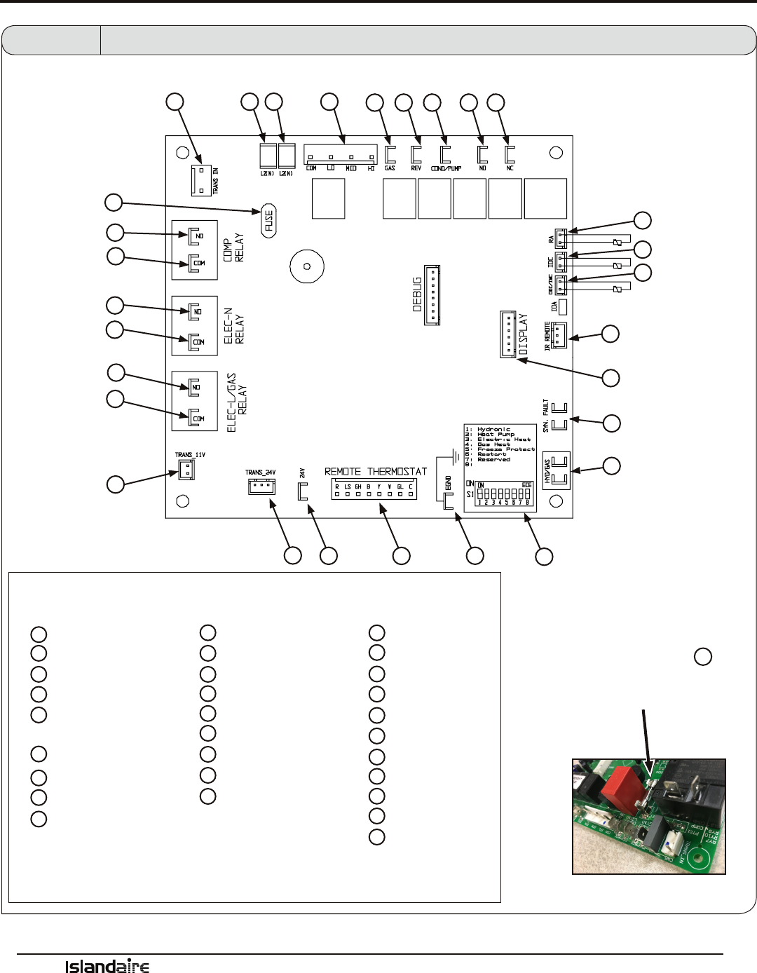
Main Control Board
Fan Con/Cyc for
heating
EGND – ACCESSORY
W
X
Y
Z
AA
BB
CC
HYD/GAS – FAN SWITCH
U T
S R
A
HI
LO
COM
P O N M
C
Q
Fuse
An easily replaceable
8.0 Amp 250V fuse V
is conveniently located
on the control board.
L
J
I
G
F
K
B
A
B
KEY
C
D
E
F
TRANS 24V
24 VAC – ACCESSORY
REMOTE THERMOSTAT
DIP SWITCH - HEAT
CONFIGURATION
G
H
I
J
K
L
M
N
O
P
SYN FAULT
IR REMOTE
ODC/IWC- OUTDOOR COIL SENSOR
IDC – INDOOR COIL SENSOR
RA – RETURN AIR SENSOR
N.C. – NORMALLY CLOSED
N.O. – NORMALLY OPEN
COND – CONDENSER MOTOR
REV – REVERSING VALVE
GAS – GAS VALVE
FAN – EVAPORATOR MOTOR
S
T
U
W
X
Y
Z
AA
BB
CC
L2(N)
L2(N)
TRANS IN
TRANS 11V
N.O. – COMPRESSOR
COM – ELEC_L
N.O. – ELEC_N
Figure 13 Main Control Board
D
E
H
DISPLAY
COM – COMPRESSOR
COM – ELEC_N
N.O. – ELEC_L
V
FUSE
V
Q
R

Manufacturer of Quality Air Conditioning and Heating Products • www.islandaire.com • sales@islandaire.com • (800)-886-2759
33
Performance Specifications
Vertical Packaged
Terminal Cooling Unit
With Heat Pump Or
Electric Heating
PART I: SPECIFICATIONS
Capacities: 9000, 12000, 15000, and 18000 BTUh
PART II: GENERAL
1.01 SYSTEM DESCRIPTION
Single piece, thru-the-wall, electrically-controlled
unit using hermetic rotary compressor for cooling
and heat pump or electric resistance heat.
A. Wall Case:
Shall be entirely constructed of galvanized,
heavy gauge, steel. Wall cases shall be attached
to the wall plenum as shown on plans and shall
have factory provisions for use of appropriate
eld supplied fastening devices to secure the
case to it. In no event shall fasteners be installed
through the basepan in the bottom of the wall
case. Wall case must have dimensions of 23 1/8
in. width by 31 in. height by 23 1/8 in. depth.
B. Outdoor Louvered Grille:
Shall be (stamped)(architectural) anodized
aluminum as show on plans. Louver shall be
(nished natural)(painted) as shown on the
schedule. Louvers shall be easily installed from
the inside of the building aer the cabinet/
wall case has been installed. Special eld fab-
ricated louvers must be approved by the VTAC
manufacturer as to free area and air circulation
requirements. e outdoor grille shall resist cor-
rosion, breakage and match the color specied
on drawing schedule and specications.
1.02 QUALITY ASSURANCE
System shall be tested and certied by ETL. Chassis
capacity and eciency performance shall be certi-
ed in accordance with AHRI standard 390. Chassis
shall meet ASHRAE Standard 90.1 for minimum
energy eciency.
1.03 DELIVERY, STORAGE AND HANDLING
A. e packaging of the chassis shall be sucient to
protect the chassis from damage during ship-
ment via an enclosed truck.
B. Chassis, wall cases/plenums and grilles shall be
shipped in separate cartons. Universal handling
instructions shall be dened and visible on the
cartons from the front, back and sides.
C. Unit shall be stored and handled per manufac-
turer’s recommendations.

Manufacturer of Quality Air Conditioning and Heating Products • www.islandaire.com • sales@islandaire.com • (800)-886-2759
34
Performance Specifications (Cont.)
E. Coils
Condenser and evaporator coils to be construct-
ed of high-eciency, aluminum ns and seam-
less axial-grooved copper tubing, necessary to
achieve EER and COP rating, as specied on the
chassis name plate.
F. Factory-Installed Electric Heater
e factory-installed, open-coil type, electric
heater is standard in heat/cool and heat pump
chassis. e electric heater shall contain both an
automatic reset and a one-shot over temperature
protection device.
e electric heating capacity shall be as identi-
ed on the Contract drawing schedule and in
the specication.
G. Front Panel (supplied with chassis)
Front panel shall be constructed of 18-gauge
galvanized steel to resist breakage and corrosion.
e air lter shall be easily accessible by from
the front of the unit.
H. Fresh Air Vent
e chassis shall have a manual open/close fresh
air vent with a concealed electric switch control.
e vent control shall allow a maximum of
72-75 CFM of fresh air to be drawn into the
room when the indoor fan is operating and the
door is open.
I. Condensate Removal System
e chassis shall have a condensate removal sys-
tem consisting of a condensate suction port, to
draw and atomize condensate, and a slinger ring
integrated in the outdoor fan, to disperse con-
densate onto the condenser coil to be evaporated
during the cooling cycle.
Condensation accumulated during the reverse
cycle heating must NOT be evaporated against
the indoor coil so as to prevent contamination of
the indoor air with pollutants and odors. Con-
densation must be disposed of using a (external)
(internal) drain system as shown on plans.
2.01 EQUIPMENT
A. General
Factory-assembled, single-piece heating and/or
cooling unit. Contained within the unit en-
closure shall be compressor, coils, fans and fan
motor, heating means, controls, all wiring and
piping, and a full refrigerant charge (R-410A).
B. Chassis
e chassis shall be a factory-assembled, single
piece heating and/or cooling unit, that is simple
to install and operate. Just slide the chassis into
a wall case and apply power.
1. Operating Characteristics
Chassis shall be capable of starting and running
at 115 °F ambient outdoor temperature per maxi-
mum load criteria of AHRI Standard 390.
2. Electrical
Chassis shall be equipped with a power cord or
hard wiring ready. e chassis current draw shall
be specied on the chassis nameplate and match
electrical requirements specied on the Contract
drawing schedule and specications. e power
cord plug conguration shall conform to NEMA
standards and the rating shall support the current
draw of the electric resistance heater.
C. Airow System
e airow system shall consist of one perma-
nent split-capacitor, direct-drive permanently
lubricated, two-speed fan motor for the indoor
(EVAP.) and outdoor (COND.) fans. e out-
door fan shall be dynamically balanced, corro-
sion-resistant polymer, multi-blade axial ow
design, with integrated slinger ring. e indoor
fan shall be dynamically balanced, sheet metal,
forward-curved blower wheel, to assure uni-
form air distribution. e fan motor shall be an
enclosed design to reduce the eects of moisture
and corrosion.
D. Compressor and Refrigerant
e rotary-type compressor shall be fully her-
metic with internal and external vibration isola-
tion. e refrigeration system will be sealed and
contain a full refrigerant charge (R-410A).

Manufacturer of Quality Air Conditioning and Heating Products • www.islandaire.com • sales@islandaire.com • (800)-886-2759
35
Performance Specifications (Cont.)
4.01 HEAT PUMP OPERATION
Heat pump units shall have the selected room tem-
perature maintained by cycling either in the heat
pump mode or electric heat. A heat pump unit with
electric heat is switched from the heat pump mode
to electric heat when the unit is on and the outdoor
coil temperature reaches 27 °F, or when the outdoor
air temperature is 35 °F and an initial call for heat is
triggered. At this time, back-up electric heat is the
only source of heat, and will only attempt to go back
to normal compressor operation aer it has been
satised.
A temperature-sensing device shall be used to
monitor the outdoor coil temperature to limit frost
buildup. Defrosting of the outdoor coil will be acti-
vated when outdoor coil temperature drops below
27 °F or outdoor air temperature drops to 35 °F or
less.
For heat pump operation, a room thermostat with
a B (heating changeover) terminal is required. is
will mean that some “auto changeover” thermostats
cannot be used, as many of them either do not have
a B terminal, or energize the B terminal continu-
ously when in the “auto” position.
Condensation accumulated during reverse cycle
heating will NOT be evaporated against the indoor
coil so as to prevent contamination of the indoor
air with pollutants and odors. Condensation must
be disposed of using an external or internal drain
system as shown on plans.
The indoor (EVAP.) fan will stop if the indoor coil
temperature falls below 78 °F. It will restart at its
set speed when indoor coil temperature rises back to
80 °F.
3.01 CONTROLS
All standard models shall be equipped with electro-
mechanical controls to simplify the serviceability of
the unit.
A. Standard Control
e chassis shall have a remote thermostat ter-
minal block to enable interface with a modern
remote wall thermostat.
B. Temperature Limiting
All standard models shall have Temperature Lim-
iting functionality built into the system controls.
e temperature limiting function allows a room
temperature setpoint range to be established, to
avoid extreme temperature settings, to maximize
energy savings.
C. Emergency Heat
Emergency Heat Switch (Heat Pump models
only), upon failure of the compressor, shall
automatically disable the compressor in heating
mode and allow the use of electric heat during
heating cycles. e Emergency Heat Switch is
active at all outdoor ambient temperatures.
D. ermostat
e chassis shall come from the factory ready for
wall thermostat installation.
E. Protection Circuits
Compressor shall have automatic reset, over
temperature and over current protection. e
fan motor shall have an inherent, automatic reset
over temperature protection. e electric heater
shall have two over temperature protectors.

Manufacturer of Quality Air Conditioning and Heating Products • www.islandaire.com • sales@islandaire.com • (800)-886-2759
36
LIMITED ONE YEAR PARTS AND LABOR PLUS ADDITIONAL
2ND THROUGH 5TH YEAR SEALED SYSTEM PART ONLY WARRANTY COVERING
ISLANDAIRE THRU-WALL AIR CONDITIONERS & HEAT PUMPS
THIS WARRANTY APPLIES TO THE AIR CONDITIONER UNIT (“THE UNIT”) THAT IS THE SUBJECT OF
THIS SALE AND IS IN LIEU OF ALL OTHER WARRANTIES EXPRESSED OR IMPLIED. THIS WARRANTY
DOES NOT APPLY TO ANY ACCESSORY THAT IS NOT A PART OF THE UNIT AS SHIPPED BY ISLAND-
AIRE. THIS WARRANTY APPLIES ONLY TO THE ORIGINAL EQUIPMENT AT THE ORIGINAL INSTAL-
LATION LOCATION. PROOF OF PROPER, ROUTINE MAINTENANCE WILL BE REQUIRED IN ORDER
TO MAINTAIN EXTENDED WARRANTY.
ISLANDAIRE the “Company” of East Setauket, New York warrants the unit free from defects in material and
workmanship under normal use and service, for the twelve-month period following the date of installation.
WARRANTY Coverage includes repair or replacement, at the Company’s option, of any defective parts that fail
under normal use for the rst 365 days aer the date of equipment installation* under the terms, conditions and
limitations of the warranty. All defective parts shall be returned within thirty days aer removal to the Company
at such locations as the Company may designate. Islandaire reserves the right to impose an inspection charge
and/or a restocking fee in cases where parts or equipment have been improperly returned as defective and/or as
being in warranty. A warranty part can only be replaced one time over the duration of the warranty period.
WARRANTY coverage also includes Labor Charges on all covered repairs performed by an Islandaire Autho-
rized Service Company in accordance with the terms, conditions and limitations of the warranty. Extra charges
such as emergency calls, nuisance calls, mileage, overtime or shipping are not covered. Check, test, and start by
an experienced person are responsibility of the installing contractor. Check, test and start shall include physi-
cally operating each unit in both cooling and heating modes and correcting any minor deciencies noted. On
occasion, wires may become disconnected or components may be dislodged from their bases as a result of rough
handling during transport, causing improper functioning of the unit. Correction of these minor conditions is
part of Check, Test, and Start.
WARRANTY Coverage of the Compressor and parts only shall continue from the 2nd through 5th year from
date of equipment installation*. Labor is not included.
ADDITIONAL SEALED SYSTEM WARRANTY Coverage includes replacement of any part of the sealed re-
frigeration system, including the compressor, evaporator, condenser and connecting tubing, that proves to be
defective from the 2nd through 5th Year from the date of installation. Labor is not included. Freight charges for
replacement and return of defective warranty parts will be the Company’s responsibility.
IN NO EVENT SHALL THE COMPANY’S MAXIMUM LIABILITY EXCEED THE SELLING PRICE OF THE
UNIT CLAIMED TO BE DEFECTIVE.
As a condition precedent to the Company’s obligation under this WARRANTY, it shall be the obligation of the
Owner during the designated WARRANTY period to furnish the following information to the Company within
three days aer unit failure: 1) Model Number and Serial Number of unit involved, 2) A full and complete
description of the problem encountered with the unit. Upon receipt of the above information, the Company
will reply to the Owner within a period not to exceed een working days, with a description of the action the
Company desires to take.
Contact the Islandaire Customer Service Department at 800-886-2759.
To validate this WARRANTY, you must complete the registration information below and return the pre-
addressed card to Islandaire within seven days of equipment installation. e actual warranty type for your
equipment is stated on the original Islandaire invoice for said equipment. Proof of installation date is required.
*Please be advised, where no Warranty Registration Card has been returned, the original date of invoice of the
equipment shall become the start date of the warranty period.
Typical Warranty
EZ REPLACEMENT GUIDE
Original Model Case
Height
Case
Width
Our Model Original Model Case
Height
Case
Width
Our Model
Amana® Keeprite®
PT 42 x 16 Series 16 42 42 Climette 18 5/16 32 CS
PB 26 x 16 Series 16 26 26 Seasonall 18 5/16 32 CS
American Air Filter® Lennox®
Enersaver Type 16 16 37 1/2 16 PTEIA Series 22 1/4 38 PT
Type 16 Hydronic 16 41 1/2 16
McQuay®
Nelsonaire Series 25 16 36 1/2 25 C/EC 27 3/8 54 1/2 EC
American Standard®
EB Series 22 30 5/8 EB
TW Series Type 41 16 36 1/2 41 J/EJ Series 14 30 JA
Type 40 Remotaire(SR) 16 1/2 37 40 K, EK and RK Series 13 15/16 36 KF
Applied Comfort®
Type EA, ES and RS 16 3/8 44 7/8 ED
DM/DMQ 18 5/16 32 CS Type NE 16 42 NE
SC Series 16 40 SC
Mueller®
SC Series 16 36 RM Climatrol 16 48 UN
Carrier® Remington®
51PH Wallmate 18 15/16 32 CS J/EJ Series 14 30 JA
Cartaret®
K, EK and RK Series 13 15/16 36 KF
Type 45 16 1/2 37 45 Type 41 16 36 1/2 41
Chromalox®
Type 45 16 1/2 37 45
Space Command 16 1/2 45 1/8 CH
Simonaire®
CAM (2 section) 15 35 1/2 CX SSK 15 3/4 41 RT
Chrysler®
15 1/2 36 CY SSEZ 15 3/4 41 RT
Climate Master®
SSCT 15 3/4 41 RT
Climate Master Series 700AD 16 36 AD
Singer®
Climate Master Series 701 16 40 1/2 C7 C/EC 27 3/8 54 1/2 EC
Climate Master
Series 702, 703 & 704
16 36 CM EB 22 30 5/8 EB
Dunham Bush®
J/EJ Series 14 30 JA
New Port III 25 52 N3 K, EK and RK Series 13 15/16 36 KF
New Port IV 25 52 N3 Type 41 16 36 1/2 41
Fedders®
Type 45 16 1/2 37 45
Maxizone Series 16 1/4 27 MX Type EA, ES and RS 16 3/8 44 7/8 ED
Unizone 16 48 UN
Slant Fin®
Friedrich®
JK 16 42 JK
Climate Master Series 700AD 16 36 AD CC Monterrey 16 42 CC
Climate Master Series 701 16 40 1/2 C7 Monterrey 17 1/2 36 FM
Climate Master Series
702, 703 & 704
16 36 CM
Suburban Dynaline®
ET Series 20 28 ET Gas Unit 16 42 GS
TE Series 16 42 TE
TPI®
Vert-I-Pak 32 23 VP Ra-Matic 16 36 RM
General Electric® Weil-Mclain
Zoneline 16 42 42 ClimateMaster Series 700AD 16 36 AD
AJ Series 16 26 26
Climate Master Series 702,
703 & 704
16 36 CM
AZ Vertical 31 23 1/4 VP
Westinghouse®
Heil Quaker®
RB Series 15 38 1/2 RB
SEA Series 14 1/2 35 7/8 HQ
Worthington®
16 48 UN
SHA Series 14 1/2 35 7/8 HQ
Zoneaire®
Series C 18 5/16 32 CS CHP Series 18 5/16 32 CS
Ice-Cap / Ice Air®
CSM Series 18 5/16 32 CS
RSK Series 16 36 RK Zoneaire‚ RM Series 16 36 RM
RSCT Series 15 3/4 41 RT Zoneaire‚ SC Series 16 40 SC
RSWL Series 13 1/4 56 1/2 WL
Custom Products
ITT Nesbitt®
Vertical Units, Fan Coils, and other related HVAC products.
(Consult with Factory)
Challenger Series 16 1/4 42 1/4 NC
Roomate Series - N - - CY
If you don’t see the unit you’re looking for in the above list, please call us
about having a unit custom designed for you.
Modular Roomate (MW) - - NR

THE C U RE FOR UN COND I T IONED MAK E-U P AIR
T M
Ask your salesman about
our DR. VTAC option!
*
*100% conditioned
fresh air
NEW!
Vertical Unit Available
For New Construction and as
Replacement for:
GE AZ Vertical, Friedrich
Vert-I-Pak and First
Company SPX
500 Middle Country Road • St. James, NY 11780 • 1-800-886-2759
e-mail: sales@islandaire.com • www.islandaire.com
Ph: 631-471-2900 • Fax: 631-471-2913
Locally Represented By:
