Installation & Operation Manual
VPAK LARGE IOM / 95991002_04
NOTE: This manual only applies to VEA 24000 and VHA 18000-24000 BTU/hr models.
For all other A-series models please refer to manual 95991001_05
US
C
VERT-I-PAK
®
A-Series
Single Package Vertical Air Conditioning System
Large Chassis

2
Warnings __________________________________________________________________________________ 3
General
Specications ______________________________________________________________________________ 4
Chassis Dimensions__________________________________________________________________________5
Electrical Data
_____________________________________________________________________________ 6
Air Flow Data
______________________________________________________________________________ 8
Installation
Minimum Clearances ________________________________________________________________________ 9
Installation Overview & Dimensions
___________________________________________________________ 10
Closet View
_______________________________________________________________________________ 11
Rough Opening Dimensions
__________________________________________________________________ 12
Wall Plenum Installation
____________________________________________________________________ 13
Louver Installation
_________________________________________________________________________ 17
Chassis Installation
________________________________________________________________________ 19
Primary Drain Installation
___________________________________________________________________ 20
Return Air & Ductwork Installation
____________________________________________________________ 21
Thermostat Installation
_____________________________________________________________________ 22
Reference
Electrical Wiring Diagram ___________________________________________________________________ 23
Final Installation Checklist___________________________________________________________________ 26
Service and Warranty
_______________________________________________________________________ 27
Diagnostic Error Codes
_____________________________________________________________________ 28
Table of Contents
3
Congratulations!
The Friedrich VPAK has been carefully engineered and manufactured to provide many years of dependable, efcient operation
while maintaining a comfortable temperature and humidity level. Many extra features have been built into the unit to ensure
quiet operation, optimal circulation of cool, dry air, and the most economic operation.
Please carefully read and follow the installation instructions and safety warnings detailed in this manual.
Refrigeration system under high pressure. Do not punc-
ture, heat, expose to ame or incinerate. Only certied
refrigeration technicians should service this equipment.
R410A systems operate at higher pressures than R22
equipment. Appropriate safe service and handling prac-
tices must be used. Only use gauge sets designed for use
with R410A. Do not use R22 gauge sets. Failure to do so
can result in property damage, personal injury, or death.
WARNING
Please read this manual thoroughly prior to equipment
installation or operation. It is the installer’s responsibility
to properly apply and install the equipment. Installation
must be in conformance with the NFPA 70-2008 National
Electric Code or current edition, International Mechanic
code 2009 or current edition and any other applicable local
or national codes.
Your safety and the safety of others are very
important.
We have provided many important safety messages in
this manual and on your appliance. Always read and
obey all safety messages.
This is the safety alert symbol.
This symbol alerts you to potential
hazards that can kill or hurt you
and others.
All safety messages will follow the
safety alert symbol with the word
“WARNING” or “CAUTION”.
These words mean:
Indicates a hazard which, if not avoided, can result in
severe personal injury or death and damage to product or
other property.
Indicates a hazard which, if not avoided, can result in
personal injury and damage to product or other property.
All safety messages will tell you how to reduce the chance
of injury, and tell you what will happen if the instructions
are not followed.
Indicates property damage can occur if instructions
are not followed.
WARNING
CAUTION
NOTICE
WARNING
Electrical shock hazard.
Turn OFF electric power before service or instal-
lation.
Unit must be properly grounded.
Unit must have correct fuse or circuit breaker pro-
tection. Unit’s supply circuit must have the correct
wire conductor size. All electrical connections and
wiring must be installed by a qualied electrician
and conform to the National Electrical Code and all
local codes which have jurisdiction. Failure to do so
can result in property
damage, personal injury and/or death.
WARNING
4
General Specications
V E A 2 4 K 3 4 RT P - A
Series
VEA = Cooling + Electric
Heat
VHA = Heat Pump +
Electric Heat
Electric
Heat Size
25 = 2.5 kW
34 = 3.4 kW
50 = 5.0 kW
75 = 7.5 kW
RT = Standard
Remote
Operation
Engineering
Code
Nominal Capacity (Btu /Hr.)
18 = 18000 24 = 24000
Marketing Code
Voltage
K = 230/208 V
R = 265 V *ONLY AVAILABLE ON VHA MODELS
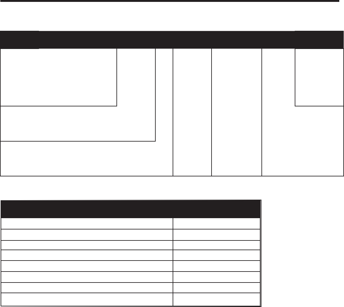
Chassis Specications VEA24, VHA18, & VHA24
Voltage 230/208 or 265
Refrigerant R-410A
Chassis Width 23 1/8”
Chassis Depth 23 1/8”
Chassis Height** 47 1/4”
Shipping W x D x H 26” x 25” x 52”
Supply Factory Collar*** 10”
Drain Connection 3/4” FPT
NOTE:
** Height includes 2” duct collar and isolators under unit
*** Factory collar accepts 10” ex duct
5
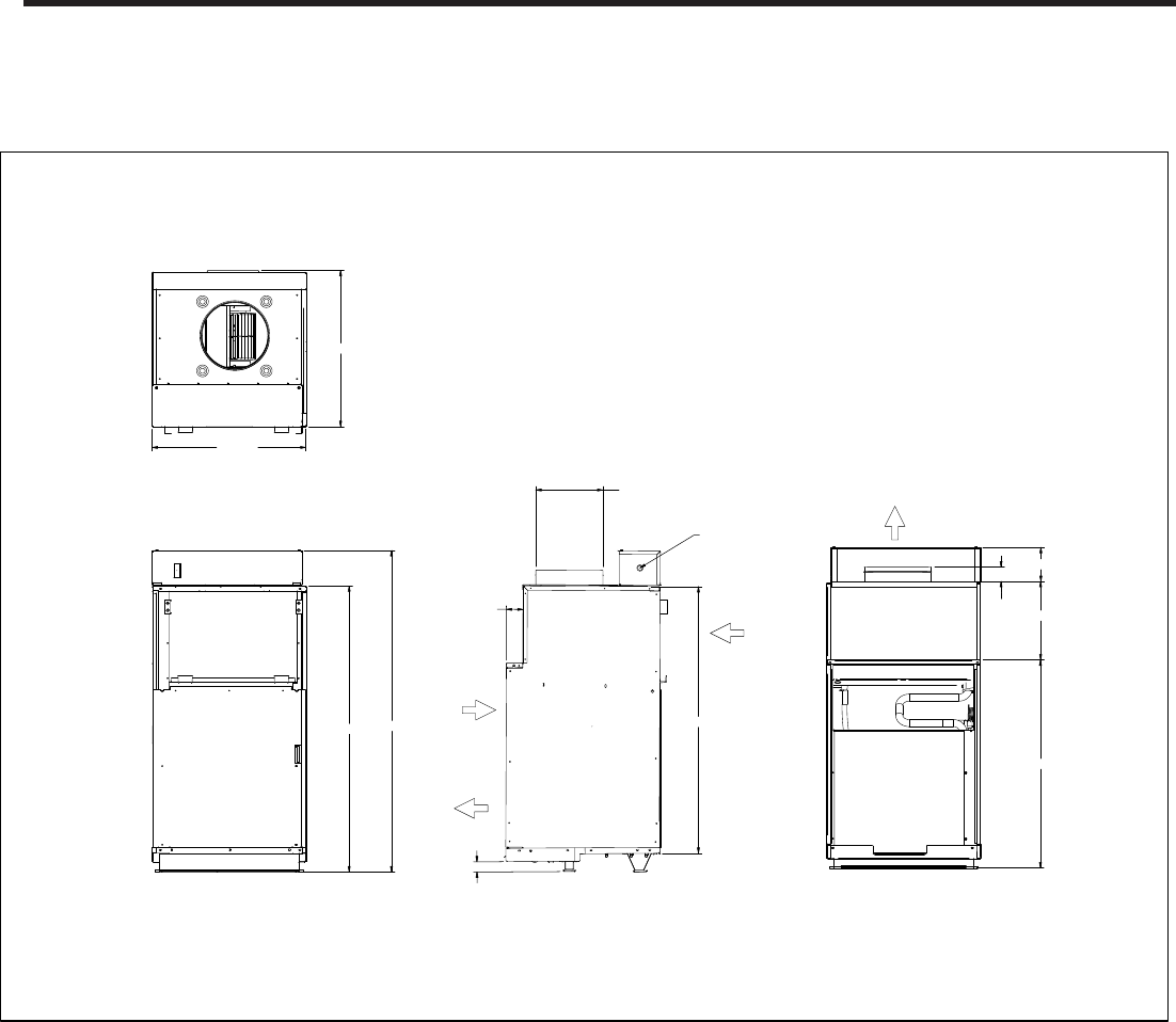
Chassis Dimensions
42 5/8
39 3/4
2 3/16
5 1/16
24 3/8
31
11 11/16
47 15/16
22 15/16
2 1/2
10
DUCT
DIAMETER
SUPPLY
AIR
RETURN
AIR
CONDENSER
INLET
AIR
ELECTRICAL
ENTRY
BOTH SIDES
CONDENSER
EXHAUST
AIR
FRONT
SIDE
REAR
TOP
1 1/2
6
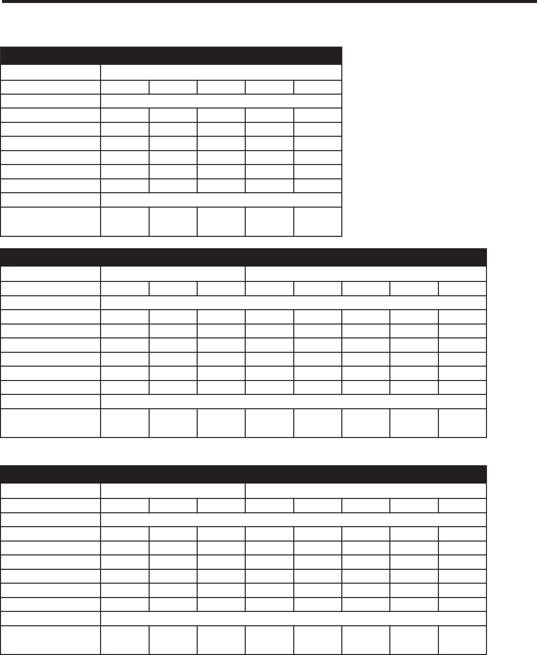
Electrical Data and Specications
VEA 230/208
MODEL VEA24K
Heater Watts
2500/2050 3400/2780 5000/4090 7500/6135 10000/8180
Voltage
230/208
Elec. Heating Current (Amps)
10.9/9.9
14.8/13.4 21.7/19.7 32.6/29.5 43.5/39.3
Minimum Circuit Ampacity
17.2 22.1 30.7 44.3 57.9
Branch Circuit Fuse (Amps)
20 25 35 45 60
LRA - Compressor (Amps)
46.0 46.0 46.0 46.0 46.0
Cooling Current (Amps)
10.0/10.4 10.0/10.4 10.0/10.4 10.0/10.4 10.0/10.4
Basic Heater Size
2.5 kW 3.4 kW 5.0 kW 7.5 kW 10.0 kW
Power Connection
HARD WIRED
Recommended Branch
Circuit Wire Sizes
* AWG-American Wire Gauge
14 12 8 6 4
VHA 230/208
MODEL VHA18K VHA24K
Heater Watts
2500/2050 3400/2780 5000/4090 2500/2050 3400/2780 5000/4090 7500/6135 10000/8180
Voltage
230/208
Elec. Heating Current (Amps)
10.9/9.9 14.8/13.4 21.7/19.7 10.9/9.9 14.8/13.4 21.7/19.7 32.6/29.5 43.5/39.3
Minimum Circuit Ampacity
14.3 19.2 27.8 17.2 22.1 30.7 44.3 57.8
Branch Circuit Fuse (Amps)
15 20 30 25 25 30 45 60
LRA - Compressor (Amps)
42.0 42.0 42.0 46.0 46.0 46.0 46.0 46.0
Cooling Current (Amps)
8.6/9.2 8.6/9.2 8.6/9.2 10.6/10.9 10.6/10.9 10.6/10.9 10.6/10.9 10.6/10.9
Basic Heater Size
2.5 kW 3.4 kW 5.0 kW 2.5 kW 3.4 kW 5.0 kW 7.5 kW 10.0 kW
Power Connection
HARD WIRED
Recommended Branch
Circuit Wire Sizes
* AWG-American Wire Gauge
14 12 10 10 10 10 6 4
VHA 265
MODEL VHA18R VHA24R
Heater Watts
2500 3400 5000 2500 34000 5000 5000 5000
Voltage
265
Elec. Heating Current (Amps)
9.4
12.8 18.9 9.4 12.8 18.9 28.3 37.7
Minimum Circuit Ampacity
12.3 16.6 27.1 12.3 16.6 27.1 38.9 50.7
Branch Circuit Fuse (Amps)
15 20 30 15 20 30 40 60
LRA - Compressor (Amps)
42.0 42.0 42.0 46.0 46.0 46.0 46.0 46.0
Cooling Current (Amps)
7.6 7.6 7.6 9.7 9.7 9.7 9.7 9.7
Basic Heater Size
2.5 kW 3.4 kW 5.0 kW 2.5 kW 3.4 kW 5.0 kW 7.5 kW 10.0 kW
Power Connection
HARD WIRED
Recommended Branch
Circuit Wire Sizes
* AWG-American Wire Gauge
14 12 10 14 12 10 6 4
7
Electrical Data and Specications
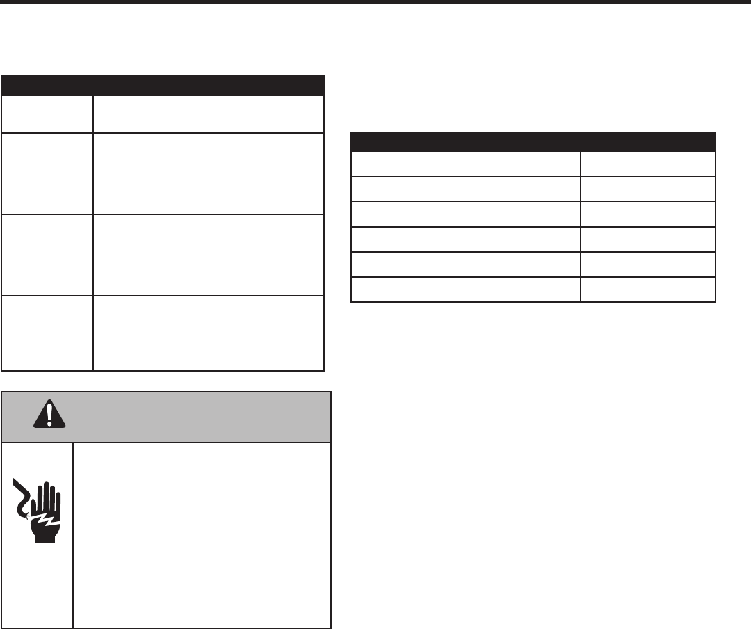
Electrical Requirements
Wire Size Use ONLY wire size recommended for
single outlet branch circuit.
Fuse/Circuit
Breaker
Use ONLY type and size fuse or HACR cir-
cuit breaker indicated on unit’s rating guide.
Proper over current protection to the units is
the responsibility of the owner.
Grounding Unit MUST be grounded from branch circuit
to unit, or through separate ground wire
provided on permanently connected units.
Ensure that branch circuit or general pur-
pose outlet is grounded.
Wire Sizing Use recommended wire size given in tables
and install a single branch circuit. All wiring
must comply with local and national codes.
NOTE: Use copper conductors only.
Electrical Rating Table
NOTE: Use copper conductors ONLY. Wire sizes are per NEC.
Recommended Branch Circuit Sizes*
Nameplate Maximum Circuit Breaker Size AWG Wiring Size**
15A 14
20A 12
30A 10
45A 6
60A 4
AWG - American Wire Gauge
* Single circuit from main box.
** Based on 100’ or less of copper, single insulated conductor at 60˚ C
NOTE: All 230/208 chassis must be hard wired with a properly sized breaker. See unit nameplate for specic electrical requirements.
Use HACR type breakers to avoid nuisance trips. All eld wiring must be done in accordance with NEC and local codes. It is the in-
staller’s responsibility to ensure that the electrical codes are met.
WARNING
Electrical Shock Hazard.
Turn OFF electric power before service or instal-
lation.
Unit must be properly grounded.
Unit must have correct fuse or circuit breaker pro-
tection. Unit’s supply circuit must have the correct
wire conductor size. All electrical connections and
wiring must be installed by a qualied electrician
and conform to the National Electrical Code and all
local codes which have jurisdiction. Failure to do so
can result in property
damage, personal injury and/or death.
8
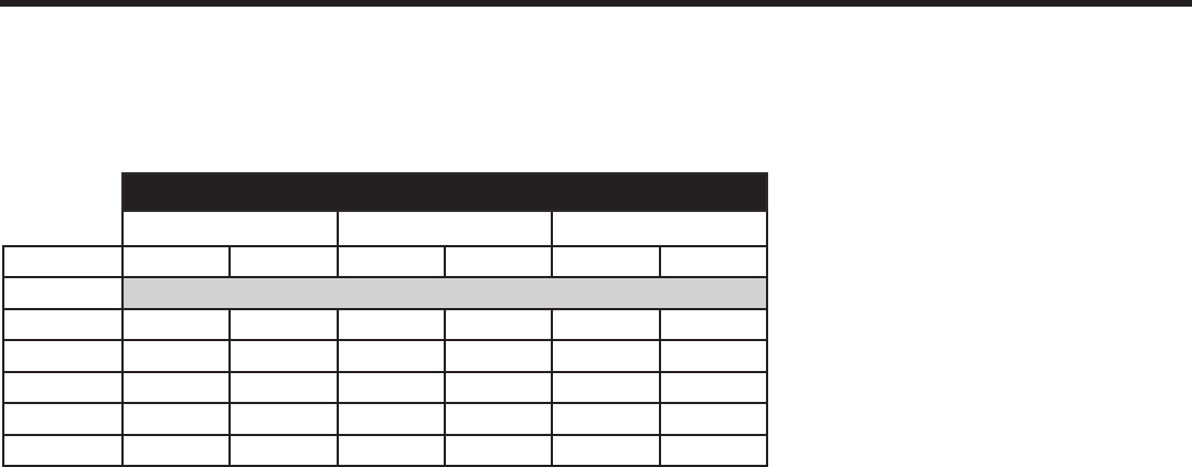
Supply Air Flow Data
Indoor CFM & External Static Pressure
Model
VEA24 VHA18 VHA24
Fan Speed
Low High Low High Low High
ESP (“)
CFM
.10”
610
700 420 465 610 700
.15”
585 670 390 420 585 670
.20”
560 640 345 380 560 640
.25”
535 610 300 325 535 610
.30”
510 580 255 280 510 580
Indoor air ow may be determined by measuring the external static pressure (ESP) of the duct system using an inclined
manometer or magnahelic gauge and consulting the above chart to derive actual air ow. Under no circumstances
should the large chassis Vert-I-Pak equipment be operated at an external static pressure in excess of 0.4” W.C. Op-
eration of the Vert-I-Pak under these conditions will result in inadequate air ow, leading to poor performance and/or
premature component failure.
Control
For LOW speed only operation, connect the fan output terminal from the thermostat to the GL terminal of the electronic
control.
For HIGH speed only operation, connect the fan output terminal from the thermostat to the GH terminal of the electronic
control.
For thermostats with two-speed capability, connect the LOW speed output to the GL terminal and the HIGH speed output
to the GH terminal.
9
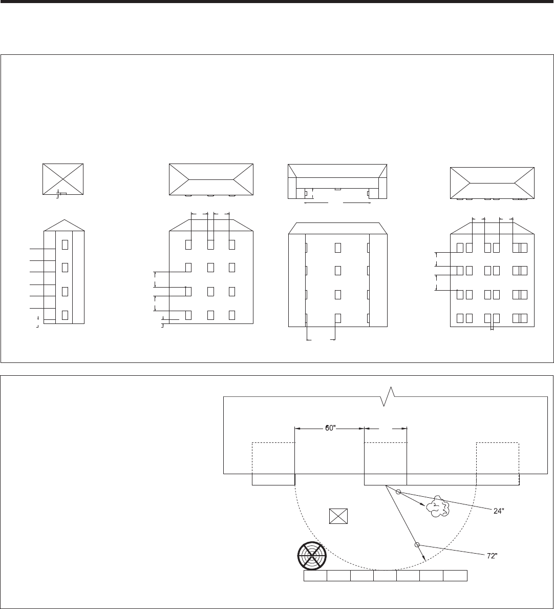
Vert-I-Pak Required Minimum Clearances
6"
60" 60"
60"
60"
60"
60"
60"
60"
60"
6"
6"
12"
60"
60"
64"
160 “
32 “
Figure A Figure B Figure C Figure D
Building Exterior Unit Opening Requirements
VPAK units must be installed on an outside wall. Conned spaces and/or covered areas should be avoided. Units must
be installed no closer than 12” apart when two units are side by side. If three or more units are to operate next to one
another, maintain a minimum of 60” between units or pairs of units (Figure B). If more than two units are sharing a oor
with adjacent, outset units, a minimum distance of 64” must be kept between units (Figure C). Also, a vertical clearance of
60” must be maintained (Figure A) between units. Units installed on the bottom oor must be mounted at least 6” off of the
ground.
Grill Clearance Requirements
Where obstructions are present use the
following guidelines for proper spacing from
the VPAK exterior louvered grill. Friedrich
recommends that ALL obstructions are a
minimum of 72” from the exhaust.
For minor obstruction(s) such as lamp poles
or small shrubbery, a clearance of 24” from
the outdoor louver must be maintained.
For major obstructions such as a solid
fence, wall, or other heat rejecting devices
like a condensing unit, a minimum distance
of 72” must be kept.
BUILDING
24"
POLE
SHRUB
FENCE
MAJOR OBSTRUCTIONS
OUTDOOR
CONDENSING
UNIT
VPAK VPAK
VPAK
The the example pictured above is for reference only and does not represent all possible installations. Please contact Friedrich
Air Conditioning for information regarding effects of other installation arrangements.
10
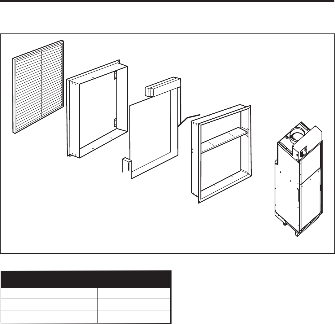
Installation Overview and Dimensional Data
VPAL2
Exterior
Wall Plenum
Exterior
Rough Opening
Interior
Wall Plenum
Chassis
Dimensions
Chassis (W x D x H) 23 1/8” x 23 1/8” x 47 1/4”
Exterior Rough Opening (W x H) 24 5/8” x 30 7/8”
Closet Rough Opening (W x H) 27” x 55 3/4”
11
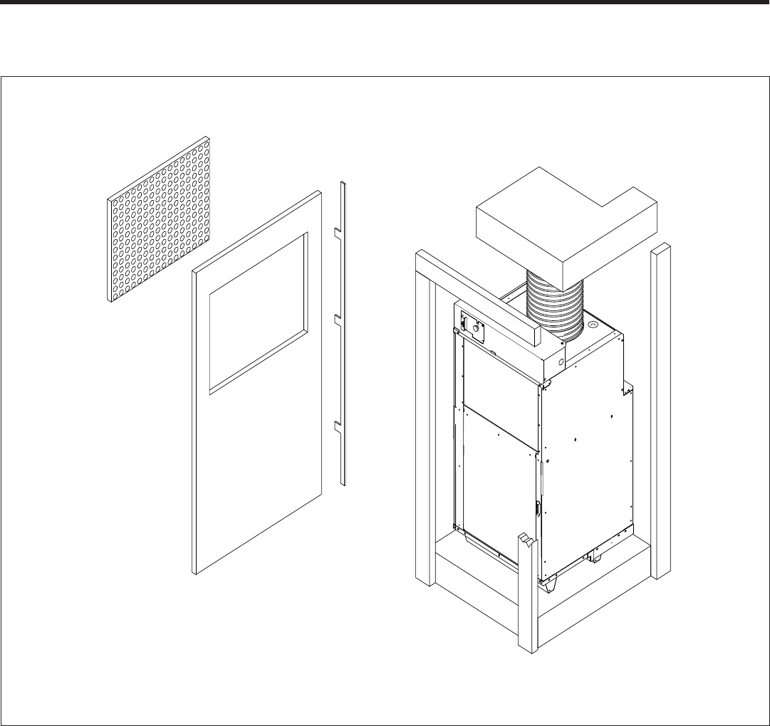
Closet View
Rigid Ductwork
Exterior Wall
Flexible
Ductwork
VPAWPX-XX
Wall Plenum
Minimum 3” clearance on all three
sides required for air ow, service,
and installation
Optional Platform
Electrical
Connection
VPRG4/R Access Panel
and Return Air Grille
Optional 25” x 20”
access panel lter
(eld supplied)
Example Closet
NOTE: It is recommended that 6” of clearance is provided on the side where the primary condensate is plumbed.
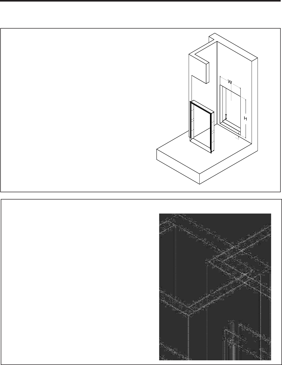
12
Dimensions (W x H):
27” x 55 3/4”
Dimensions (W x H):
24 5/8” x 30 7/8”
Wall Opening Dimensions
NOTE: The distance between the rough opening and
the nished oor/platform must be 1 1/2”. If the in-
stallation will utilize an auxiliary drain pan it may not
exceed 1 1/2” in height.
1 1/2”
Return Air Access Door Wall Cut-Out
27”
55 3/4”
Exterior Wall Plenum Cut-Out
13
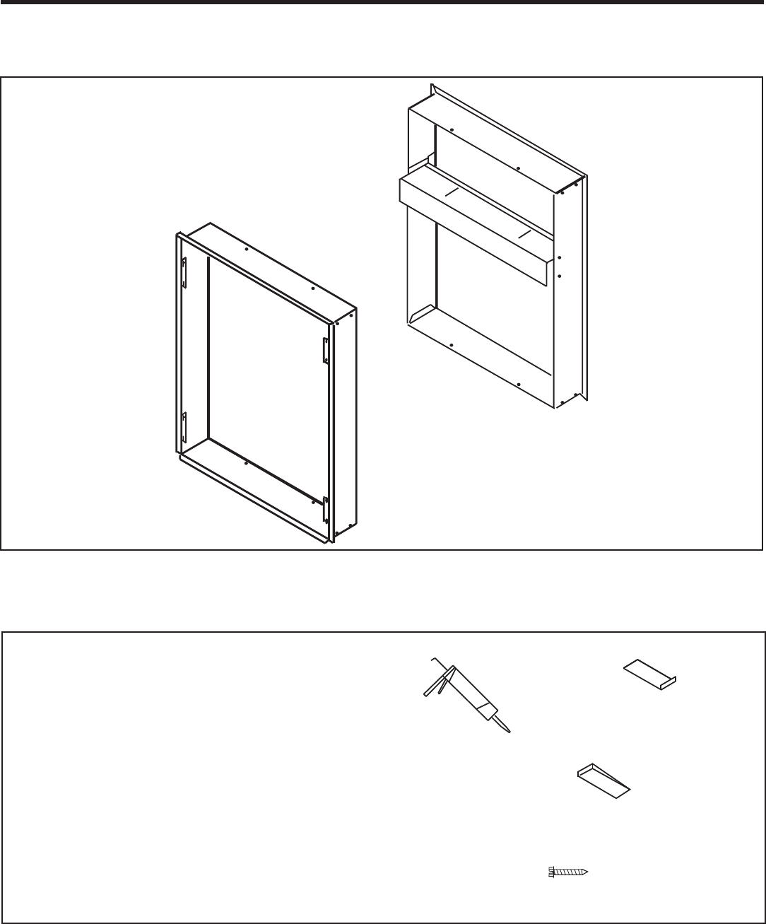
Wall Plenum Installation
A
B
Parts included in Plenum kit:
Outside Plenum Half (Part A)
Inside Plenum Half (Part B)
Field Supplied Parts:
Sealant, attachment screws, and ashing
are eld supplied. Silicone sealant is recommended.
VPAWP-8 adjust for walls up to 4”- 8” thick.
VPAWP-14 adjust for walls up to 8” - 14” thick
All installations are similar.
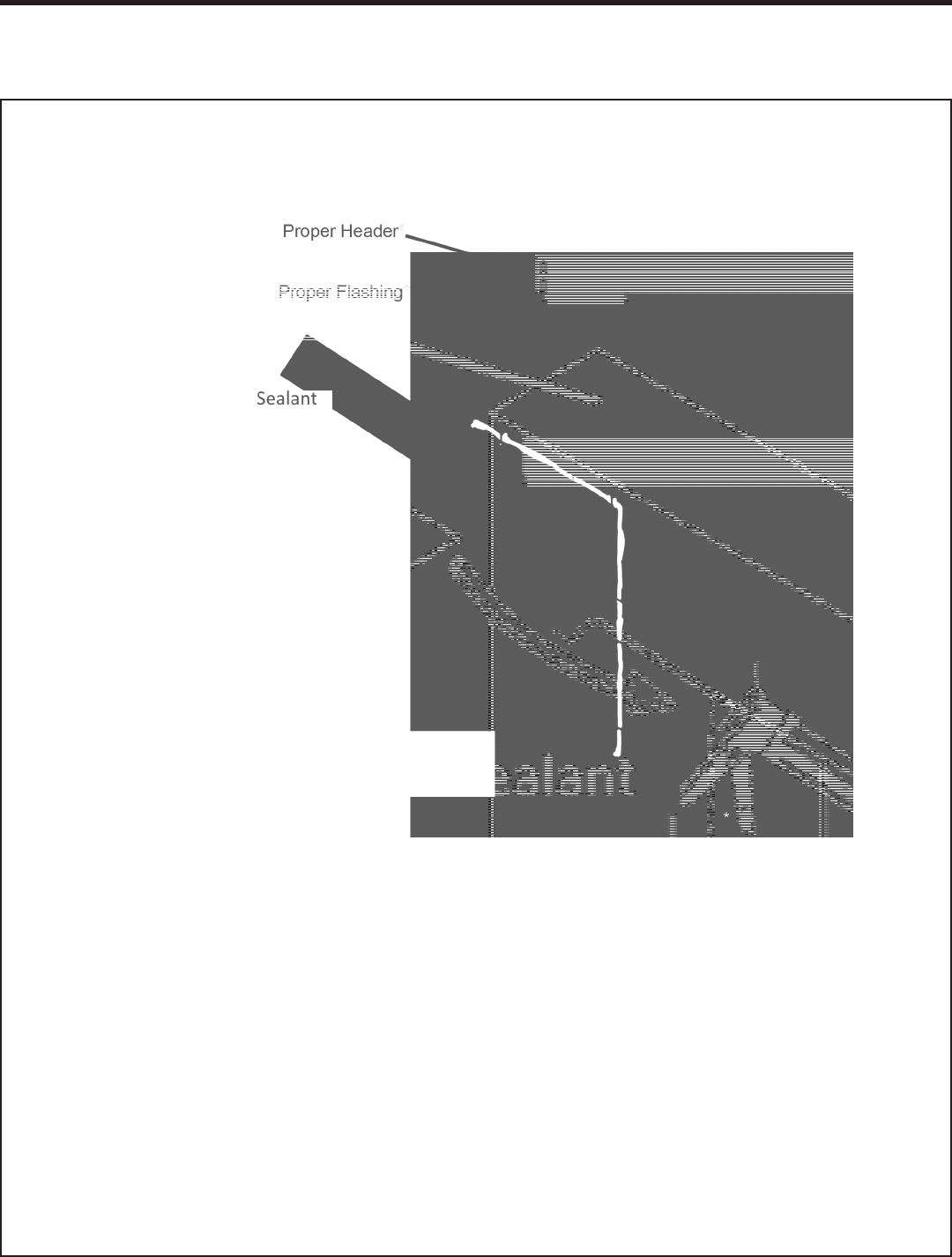
Flashing
1”-3” screws to at-
tach the plenum
assembly to the wall
studs
Sealant
Shim
14
Wall Plenum Installation
Note: The wall plenum is not designed to carry any structural load. A load bearing header must be built above
the rough opening.
1. Prepare the rough opening. The rough opening should be lined with metal or wood. The plenum will warp if
sealed against concrete or brick.
2. Dry t the outside plenum half into the rough opening and check the t and level.
3. Remove the outside plenum half, ash the rough opening to ensure proper t and level.
4. Pre-installing the exterior louver (VPAL2) as shown above is optional (See Page 17).
5. Apply sealant to the outside plenum half and insert into the rough opening to ensure a water-tight seal.
Ensure that the outside plenum half is securely attached to the framed opening.
Step 1 - Outside Wall Plenum Half
15
Wall Plenum Installation
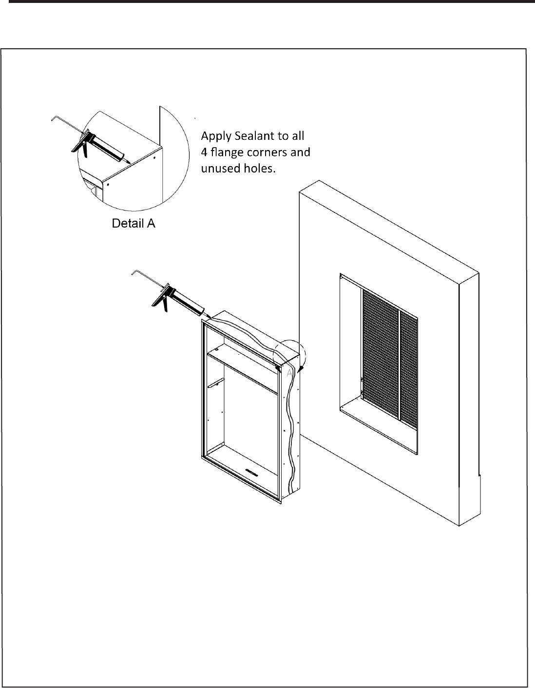
Step 2 - Inside Wall Plenum Half
Caulk all 8
Flange Corners
and Unused
Holes
Detail A
1. Apply sealant to all 4 ange corners and unused holes. See Detail A.
2. Flash the inside of the rough opening to ensure the proper t and level.
3. Insert inside plenum half (Part B) into outside plenum half (Part A). Ensure that Part A does not back out of
the rough opening.
4. Remove the inside plenum half.
5. Apply sealant to the outside plenum half and insert into the rough opening to ensure a water-tight seal.
16
Wall Plenum Installation
B
Detail B
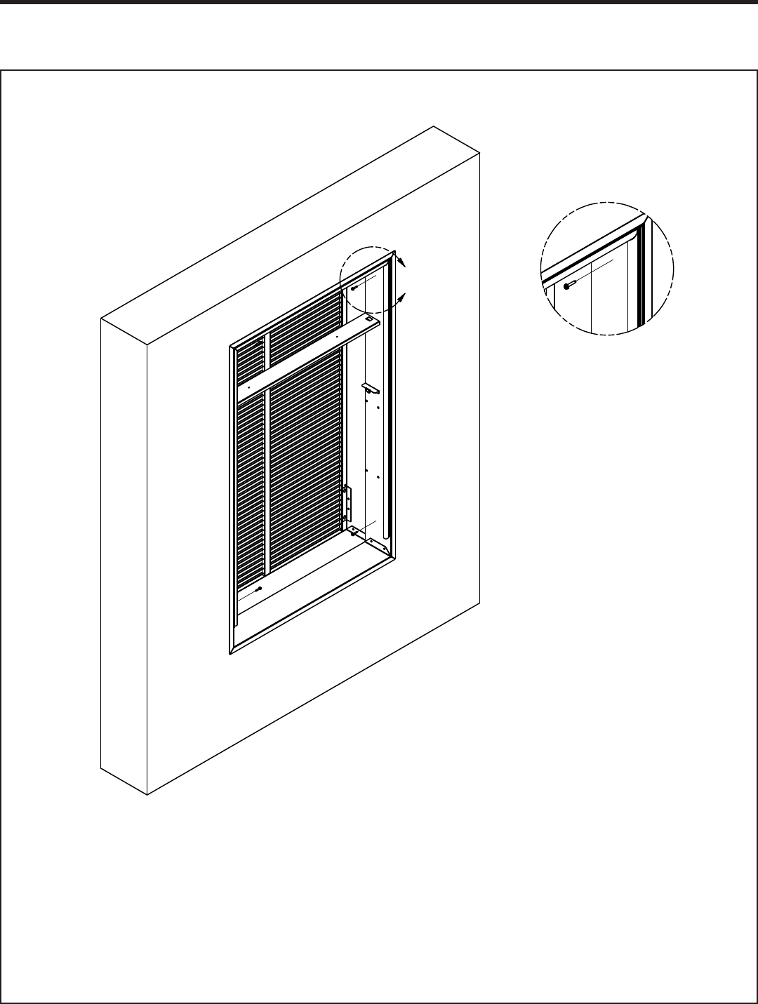
Step 3 - Inside Wall Plenum (cont.)
NOTE: Do not place any screws, fasteners, or penetrating holes through the top or bottom of the plenum
assembly.
1. Drill pilot holes on the interior of the inside plenum half (Part B) as show in Detail B. Pilot holes should be
located approximately 4” from the top and bottom of the inside plenum half, on both the left and right sides.
2. Install fasteners through each pilot hole. Fastener must pass through both Part A and Part B. If the inside
and outside plenum halves do not overlap at fastening point, be certain to drill extra holes where needed to
secure both Part A and Part B to the rough opening.
17
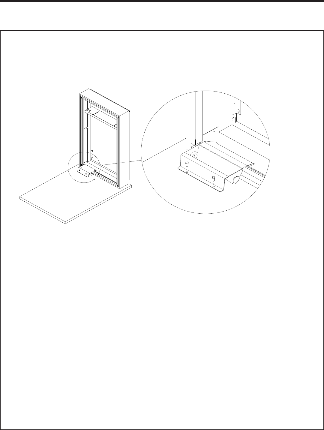
Drain Kit Installation
A
Step 4 - VPDP1 Installation
NOTE: VPDP1 (Drain Kit) should be installed prior to the installation of the chassis.
1. Cut the weather seal gasket at the left corner of the plenum.
2. From the initial cut, measure 8” toward the center of the plenum and make a second cut.
3. Peel away the cut section of gasket from the plenum surface.
4. Run a 1/4” bead of sealent the entire width of the removed gasket.
5. Insert the drain kit with the overow lip toward the plenum and ensure it is ush.
6. Finish installation with the eld supplied parts.
18
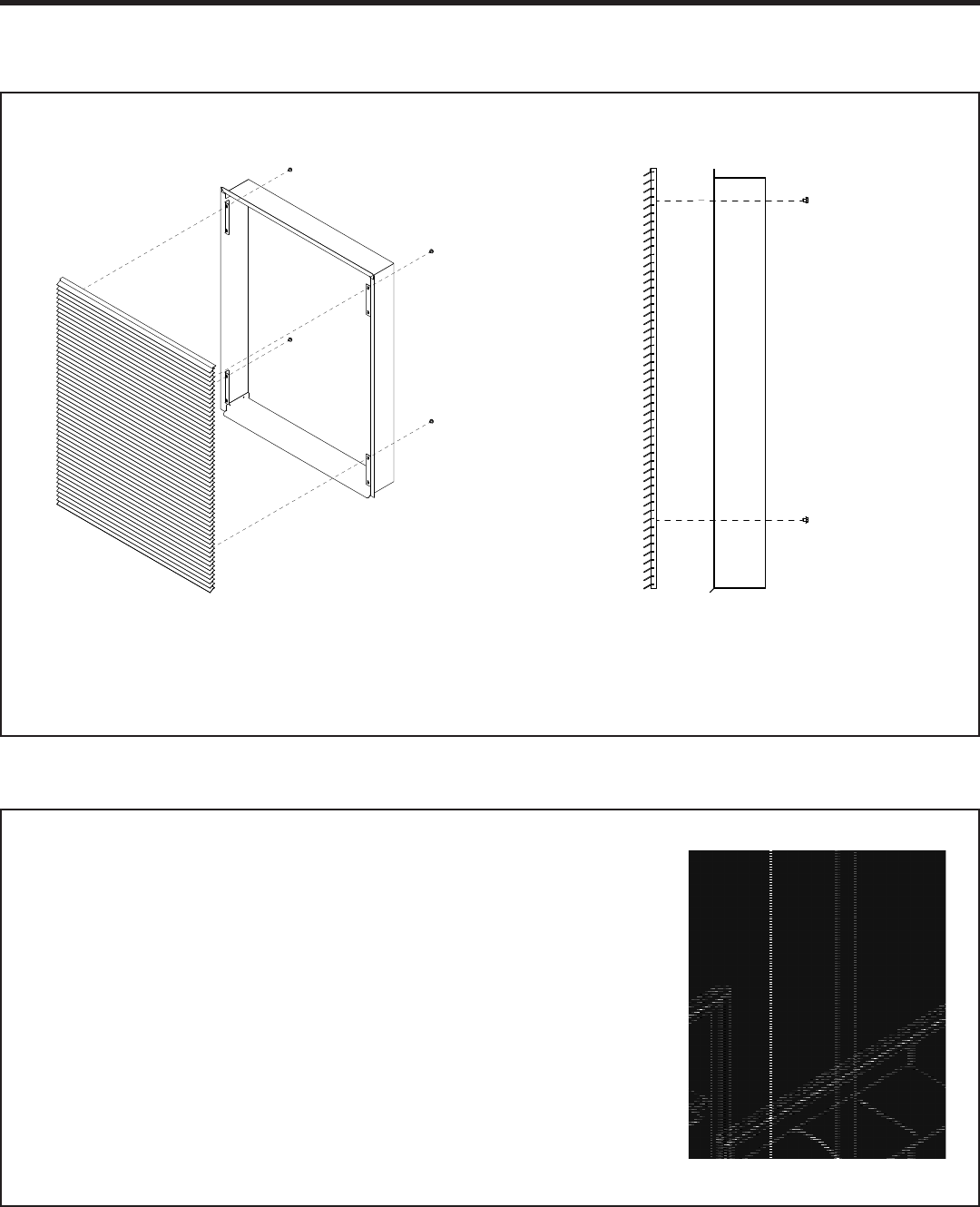
Louver Installation
Installation of the louver PRIOR to wall plenum installation
1. Hold the louver up to the outside plenum half (Part A) and line up the louver top with the very top edge of the ¾”
ange.
2. Line up the wall plenum holes with the threaded holes in the louver and securely tighten fasteners.
Installation of the louver AFTER the installation of wall plenum on
elevated oors
From the interior of the utility closet:
1. Tie a rope or tether to the architectural louver and the divider in
the wall plenum to prevent it from falling if dropped.
2. Turn the louver sideways and push the louver out below the
divider in the wall plenum.
3. Pull the louver back against the wall plenum and align the holes.
4. Insert and tighten all eight provided fasteners. When the louver
is secured, remove the safety tether.
19
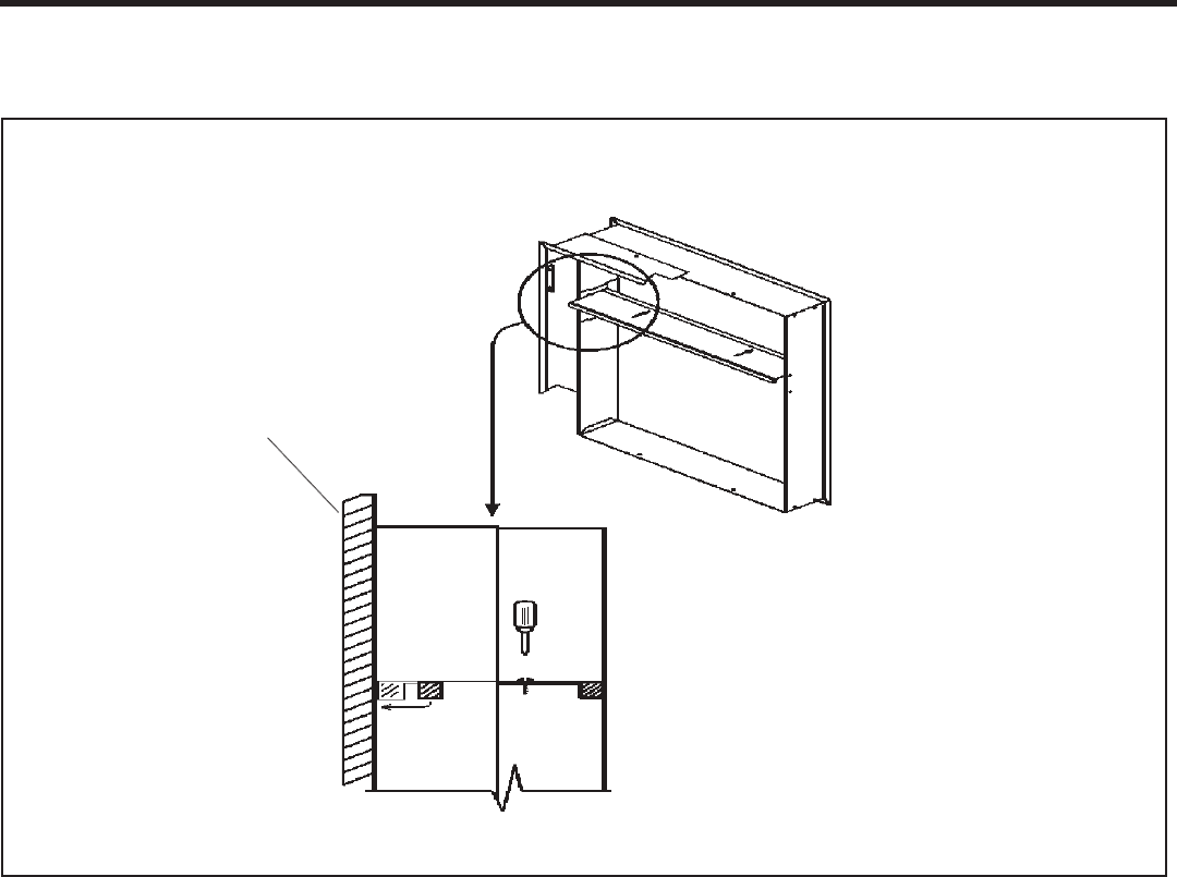
Final Wall Plenum and Architectural Louver Installation
NOTE: Ensure that the weather strip is undamaged and provides a continuous
seal around the inner perimeter of the plenum.
Apply silicone grease or other non-petroleum-based lubricants to the weather strip to enhance the sealing
capability of the weather strip and ease installation of the air conditioner chassis.
1. Loosen the two set screws located on the top side of the divider.
2. Slide the top part of the divider toward the outside until the sealing strip makes contact with the exterior
louver.
3. Tighten the set screws to complete the adjustment.
NOTE: Let all ashing cure completely before installing the chassis.
Louver
20
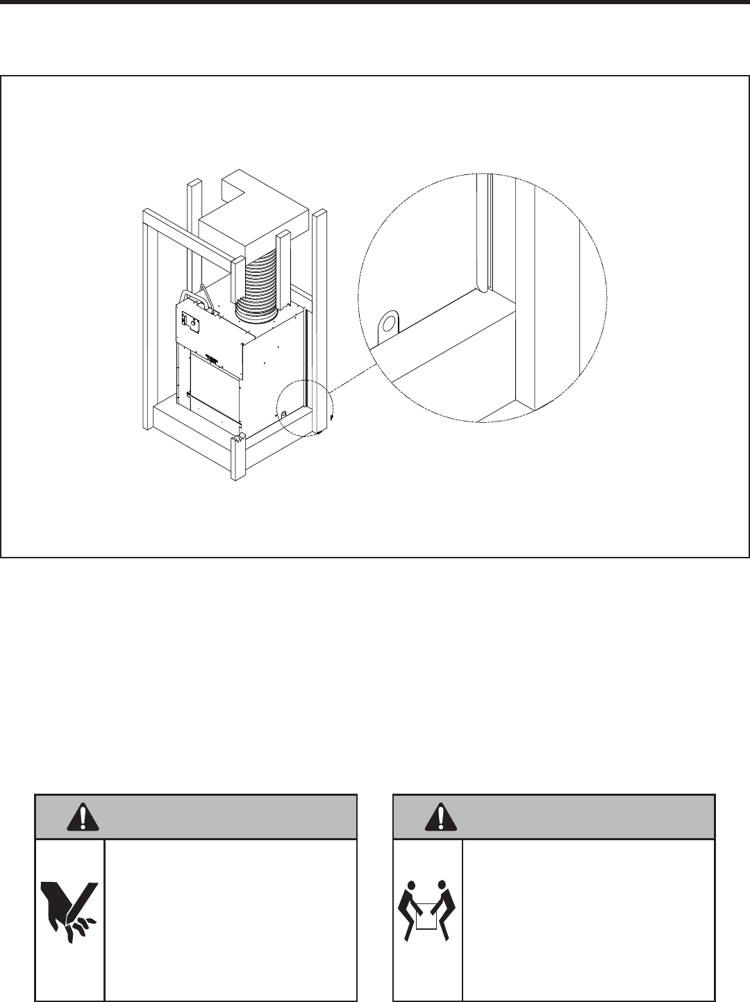
A
Chassis Installation
CAUTION
Excessive Weight Hazard
Use two or more people when installing your air
conditioner.
Failure to do so can result in back or other injury.
CAUTION
Cut/Sever Hazard
Some edges may be sharp.
Use gloves or other hand protection when han-
dling the unit.
Failure to do so can result in minor to moderate
personal injury
1. Ensure that the wall plenum and louver are installed in accordance with the instructions listed on pages 13-18.
2. Place the chassis into the closet with the outdoor side facing the wall plenum opening.
3. Slide the chassis into the wall plenum until the plenum divider seal is established.
NOTE: The Vert-I-Pak chassis must be inserted into the wall plenum so that the plenum divider gasket makes contact with
the plastic condenser bafe on the unit. The chassis will t approximately 2 3/8” into the wall plenum.
21
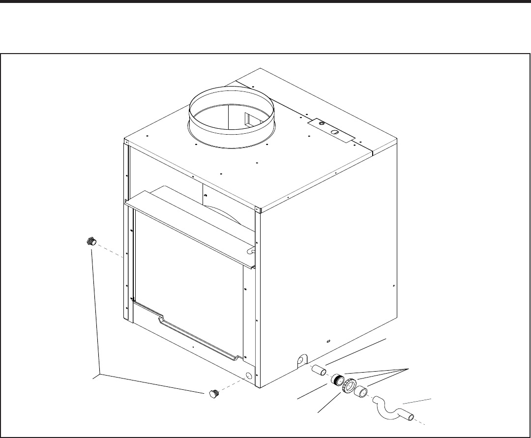
Nipple 3/4” PVC/NPT
Union 3/4” FTP/SLIP
Example of field
supplied DWV system
Threaded end
Slip end
Supplied 3/4” plugs
Primary Drain Installation
NOTE: Failure to follow the following procedures may result in serious property damage. A eld supplied secondary con-
densate pan or P-trap may be required. Check with local codes. In case of drainage system blockage, the unit base will
allow excess water to ow out of the unit through the plenum and the architectural louver. It is critical to ensure that the
drainage path is not blocked or obstructed in any way during installation.
1. The supplied drain kit must be connected to one of the two 3/4” FPT connections on the VPDP1.
2. Insert the provided 3/4” nipple into the determined connection using eld-supplied Teon tape or pipe joint
compound.
3. With the slip end of a 3/4” union, connect to the nipple with Teon tape or pipe joint compound.
4. Hand-tighten all ttings to prevent damage to unit or ttings.
5. Install a eld-supplied drain system to the slip end of the union. A trap is recommended and drain connections
should be connected to building DWV system. Pitch the drain line of a 1/4” downward slope for every foot (1’) of
lateral horizontal run to the DWV.
6. Plug the unused connection port on the VPDP1 with the provided 3/4” pipe plug with eld-supplied Teon tape or
pipe joint compound. Hand tighten to prevent damage to the unit or ttings. Do not thread metal or copper pipe
ttings directly into unit.
7. Check the system for leaks.

22
Indoor Return Air Grille and Ductwork Installation
Option 1 Option 2
VPRG4/R Return Air Grille with Access Panel
A eld-supplied (25” x 20”) can be mounted inside
the hinged access door. The door can be installed
with the grille oriented at the top of the panel for
improved sound attenuation.
NOTE: All Vert-I-Pak chassis are shipped with a 20” x 14” lter installed. If a different lter holder or location is to be used,
the lter on the chassis MUST be removed.
Ductwork
The supply duct system should be designed using a recognized method such as the equal fraction or velocity reduction
method, using the appropriate duct calculator(s) for the type(s) of duct being used in the system. The duct system should
be designed for a maximum friction rate of .3” water column taking into consideration all ttings, registers and/or diffus-
ers.
NOTE; Do not operate the unit without a supply duct attached. The return air to the Vert-I-Pak unit MUST NOT be ducted
and all units must have a free return air conguration to perform properly.
Field Supplied Return Air Grille
A eld supplied return air grille divorced from the
access panel must have a minimum 250 square
inches of free area.
23
Remote Thermostat
All Friedrich Vert-I-Pak units are factory congured to be
controlled by using a single stage heat/cool remote wall
mounted thermostat. The thermostat may be auto or
manual changeover as long as the control conguration
matches that of the Vert-I-Pak unit.
To connect the wall mounted thermostat:
1. Pull the disconnect switch.
2. Unscrew and remove the control box panel.
3. Select which side to run your thermostat wire.
4. Run the wires through the side hole in the box to
reach the connection terminal wiring.
5. Make the connections, appropriately matching the
wires as shown in the wiring diagram.
6. Reattach the control box cover.
Front Desk Control Terminals
The Friedrich Vert-I-Pak has built-in provisions for con-
nection to an external switch to control power to the unit.
The switch can be a central desk control system door
switch.
For desk control operation, connect on side of the switch
to the D1 terminal and the other to the D2 terminal.
When the circuit is closed, unit operation will stop.
NOTE: The desk control system and switches must be
eld supplied.
Maximum Wire Length for Desk Control Switch
Auxiliary Fan Control
The Friedrich Vert-I-Pak also has the ability to control a
24VAC relay to activate an auxiliary or transfer fan. The
outputs are F1 and F2 on the control board.
To connect the relay, simply wire one side of the relay to
F1 and the other side to F2.
NOTE: The relay and auxiliary fans must be eld sup-
plied. The relay must be 24VAC @ 100mA or less.
Interface Denition
NOTE: It is the installer’s responsibility to ensure that all
control wiring connections are made in accordance with
the installation instructions. Improper connection of the
thermostat control wiring and/or tampering with the
unit’s internal wiring can void the equipment warranty
and may result in property damage, personal injury, or
death. Questions concerning proper connections to the
unit should be directed to the factory.
Remote Thermostat and Low Voltage Control Connection
AWG Wire Size Maximum Length (ft.)
24 400
22 600
20 900
18 1500
16 2000
Terminal Code Wire Connection Function
C Common Ground Terminal
GH Call for High Fan
GL Call for Low Fan
B Call for Heat Pump (Reversing Valve)
Y Call for Compressor
W Call for Heating (Electric)
R 24VAC to Wall Thermostat
24
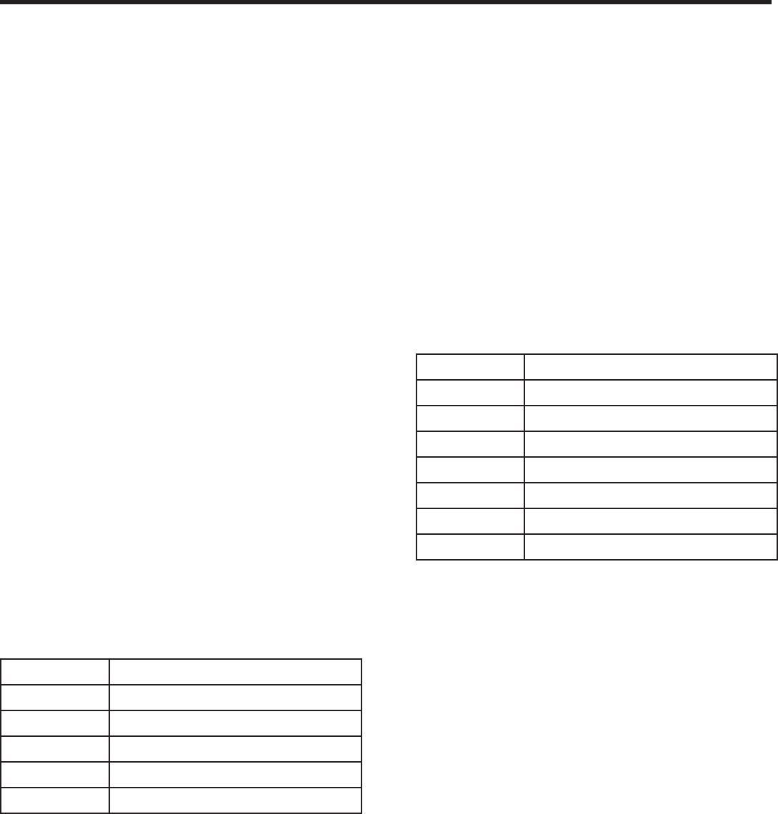
VEA 230/208 Electrical Wiring Diagram
B
L
U
E
RED
WHITE
WHITE
GREEN
BROWN
ORANGE
C
H
E
R
M
F
A
N
L1
L2
ELECTRONIC CONTROL
"
F
"
R
S
C
TERMINAL DETAIL
BLACK
B
L
A
C
K
BLUE
HEATER
2.5 KW & 3.4 KW
5.0 KW
BLACK (TO L1)
RED
QUICK
DISCONNECT
CAPACITOR
BLOWER
MOTOR
TO MOTOR
MOUNT
W
H
IT
E
5
2
0
(
T
O
L
2
)
COMPRESSOR
GASKET
TEMINAL COVER
WASHER
NUT
HARNESS
COMPRESSOR
W Call for Heating
B Reversing valve Energized in heating mode
GL Call for Low Fan
GH Call for High Fan
R 24VAC Power From Unit
Y Call for Cooling
05
PART NO. REV
LEGEND
92160001
LEGEND FOR TSTAT WIRING HARNESS
C COMMON
FUSE HOLDER
FUSE
BLACK
INDOOR COIL SENSOR
OUTDOOR COIL SENSOR
SERVICE DISPLAY
AMBIENT
AIR SENSOR
L2 or ACN
L1
VOLTAGE SELECTION SWITCH
SET VOLTAGE TO 230V
RV
RELAY
FAN 4
RELAY
FAN 3
RELAY
FAN 2
RELAY
FAN 1
RELAY
HEAT
RELAY
HEAT
RELAY
COMP
RELAY
VOLTAGE SWITCH
WIRING DIAGRAM
COOL, ELECTRIC HEAT
SMALL CHASSIS, 230/208V
HEATERS: 2.5KW, 3.4KW, 5.0KW
25
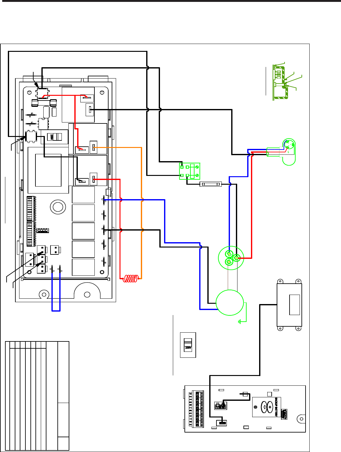
VHA 230/208 Electrical Wiring Diagram
B
L
U
E
RED
WHITE
WHITE
BLACK
GREEN
BROWN
ORANGE
C
F
A
N
L1
L2
ELECTRONIC CONTROL
"
F
"
R
S
C
TERMINAL DETAIL
BLACK
B
LA
C
K
BLUE
HEATER
2.5 KW & 3.4 KW
5.0 KW
BLACK (TO L1)
B
L
A
C
K
RED
QUICK
DISCONNECT
COIL
SOLENOID
CAPACITOR
BLOWER
MOTOR
TO MOTOR
MOUNT
W
H
IT
E
5
2
0
(
T
O
L
2
)
COMPRESSOR
GASKET
TEMINAL COVER
WASHER
NUT
HARNESS
COMPRESSOR
W Call for Heating
B Reversing valve Energized in heating mode
GL Call for Low Fan
GH Call for High Fan
R 24VAC Power From Unit
Y Call for Cooling
05
PART NO. REV
LEGEND
LEGEND FOR TSTAT WIRING HARNESS
92160301
C COMMON
BLACK
H
E
R
M
FUSE
FUSE HOLDER
INDOOR COIL SENSOR
OUTDOOR COIL SENSOR
SERVICE DISPLAY
AMBIENT
AIR SENSOR
L2 or ACN
L1
VOLTAGE SELECTION SWITCH
SET VOLTAGE TO 230V
RV
RELAY
FAN 4
RELAY
FAN 3
RELAY
FAN 2
RELAY
FAN 1
RELAY
HEAT
RELAY
HEAT
RELAY
COMP
RELAY
VOLTAGE SWITCH
WIRING DIAGRAM
COOL, ELECTRIC HEAT, HEAT PUMP
SMALL CHASSIS, 230/208V
HEATERS: 2.5KW, 3.4KW, 5.0KW
(IF APPLICABLE)
26
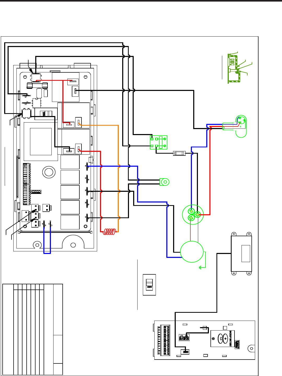
VHA 265 Electrical Wiring Diagram
B
L
U
E
RED
WHITE
BLACK
GREEN
BROWN
BLACK
C
F
A
N
L1
L2
ELECTRONIC CONTROL
"
F
"
R
S
C
TERMINAL DETAIL
BLACK
W
H
I
T
E
BLUE
HEATER
2.5 KW & 3.4 KW
5.0 KW
B
L
A
C
K
WHITE
QUICK
DISCONNECT
COIL
SOLENOID
CAPACITOR
MOTOR
TO MOTOR
MOUNT
B
L
A
C
K
COMPRESSOR
GASKET
TEMINAL COVER
WASHER
NUT
HARNESS
COMPRESSOR
W Call for Heating
B Reversing valve Energized in heating mode
GL Call for Low Fan
GH Call for High Fan
R 24VAC Power From Unit
Y Call for Cooling
03
PART NO. REV
LEGEND
LEGEND FOR TSTAT WIRING HARNESS
92160303
C COMMON
BLACK
H
E
R
M
F
U
S
E
F
U
S
E
H
O
L
D
E
R
ORANGE
RED
RELAY
BLACK
RED
B
L
A
C
K
B
L
A
C
K
R
E
D
B
R
O
W
N
WHITE
BLACK
GROUND TO CHASIS
BUILDING
GROUND
265V 60Hz
2Ø 2 WIRES
FLA
MCA
MOP
FUSE
BLOCK
TRANSFORMER
W
H
I
T
E
INDOOR
COIL
SENSOR
OUTDOOR COIL SENSOR
SERVICE DISPLAY
AMBIENT
AIR SENSOR
L2 or ACN
L1
VOLTAGE SELECTION SWITCH
SET VOLTAGE TO 230V
RV
RELAY
FAN 4
RELAY
FAN 3
RELAY
FAN 2
RELAY
FAN 1
RELAY
HEAT
RELAY
HEAT
RELAY
COMP
RELAY
VOLTAGE SWITCH
WIRING DIAGRAM
COOL, ELECTRIC HEAT, HEAT PUMP
SMALL CHASSIS, 265V
HEATERS: 2.5KW, 3.4KW, 5.0KW
F
U S
E
A
F
U S E
A
F
U S E
A
JUMPER
WIRE
TRANSFORMER
ELECTRONIC CONTROL
(REAR VIEW)

27
Final Installation Checklist
Final Installation Checklist
Inspect and ensure that all components and
accessories have been installed properly and
that they have not been damaged during the
installation process.
Ensure that all installation instructions
concerning clearances around the unit have
been adhered to.
Check to ensure that the unit air filter, indoor
coil, and outdoor coil are free from any
obstructions.
Ensure that the circuit breaker(s) or fuse(s)
and supply circuit wire size have been sized
correctly.
Check the condensate water drain(s) to
ensure that they are adequate for the
removal of condensate water and that they
meet approval of the end user.
Ensure that the entire installation is in
compliance with all applicable national and
local codes and ordinances having
jurisdiction.
Secure all access panels (i.e. front cover
and/or control box), apply power to the unit
The unit commissioning should be done at
this time to ensure unit function.
NOTE: Maintaining a log for recording the dates
of maintenance and/or service is recommended,
and should be suggested to the owner or
operator of the equipment.
Present the owner or operator of the
equipment with the Installation & Operation
Manual, all accessory installation
instructions, and the name, address and
telephone number of the Authorized Friedrich
Warranty Service Company in the area for
future reference if necessary.
Chassis Operation
Cooling Operation
The set point must be at least 3°F below room
temperature to ensure compressor operation.
In the cooling mode, when demand is present, the
indoor blower and outdoor fan will operate. The
compressor will vary operating speed to maintain
desired set point.
Heat Pump Operation
The set point must be greater than 3°F but not
greater than 6°F above room temperature to ensure
compressor operation.
In the heating mode, when demand is present, the
indoor blower and outdoor fan will operate. The
compressor will vary operating speed to maintain
desired set point.
Electric Heat Operation
If the set-point is greater than 6°F above room
temperature, the heat pump operation will be
terminated and the electric heater will be energized
to satisfy the heating demand.
If heat pump operation is not available due to
defrost or error, the electric heater will be used to
satisfy heating demand.
FreshAire™
The FreshAire™ System (optional) delivers outside
air to the indoor space. The module has a fan that
draws outdoor air into the module. The outdoor air
leaves the module through a filter and enters the
indoor space in front of the indoor conditioning coil.
The outdoor air mixes with the return air and is
drawn through the indoor conditioning coil. The
optional module can be configured as either a single
(F option) or a dual (D option)..
Inspect and ensure that all components and
accessories have been installed properly and
that they have not been damaged during the
installation process.
Ensure that all installation instructions
concerning clearances around the unit have been
adhered to.
Check to ensure that the unit air lter, indoor
coil, and outdoor coil are free from any
obstructions.
Ensure that the circuit breaker(s) or fuse(s) and
supply circuit wire size have been sized correctly.
Check the condensate water drain(s) to ensure
that they are adequate for the removal of
condensate water and that they meet approval of
the end user.
Ensure that the entire installation is in
compliance with all applicable national and local
codes and ordinances having jurisdiction.
ENSURE THAT THE SUPPLY VOLTAGE TO THE
UNIT IS WITHIN THE OPERATING RANGE
Secure all access panels (i.e. front cover and/or
control box), apply power to the unit.
The unit commissioning should be done at this
time to ensure unit function.
NOTE: Maintaining a log for recording the dates
of maintenance and/or service is recommended,
and should be suggested to the owner or
operator of the equipment.
Present the owner or operator of the equipment
with the Installation & Operation Manual, all
accessory installation instructions, and the name,
address and telephone number of the Authorized
Friedrich Warranty Service Company in the area
for future reference if necessary.
NOTE: The unit is not designed to guarantee
continuous operation with outdoor ambient
conditions greater than 110F.
•
•
•
•
•
•
•
•
•
Chassis Operation
Fresh Air Door
The fresh air door is an “intake” system. It is
opened via a slide mechanism on the front of the
chassis located just above the indoor coil. Move
the slide left to open and right to close the door.
The system is capable of delivering up to 60 CFM of
outdoor air.
Low Ambient Compressor Cut Out
Each chassis is equipped with low ambient
protection that is determined by thermistor
feedback. The feedback will prevent the
compressor from operating at low suction
temperatures.
Room Freeze Protection
This feature will monitor the indoor room
conditions and in the event that the room falls
below 40F, the unit will cycle on high fan with the
electric heater. This occurs regardless of mode.
28
Inspect and Clean Indoor Air Coil
Eventually, minor amounts of lint and dirt may pass
through the lter and collect on the indoor-air coil. These
minor accumulations can be carefully vacuumed away
with a brush attachment on a vacuum cleaner. Care must
be taken to avoid bending the aluminum ns on the coil.
Bent ns should be straightened using a special n tool
available from most HVAC supply depots.
Inspect Outdoor Air (OA) Intake and Exhaust
The unit’s outdoor-air intake and outdoor-air exhaust paths
must remain clear. Keep it free of all debris, snow, or ice.
The OA intake should also be kept free of obstructions.
Blocking the OA exhaust or OA intake opening will reduce
the efciency of your unit and could damage it.
Inspect and Clean Condensate Drain
The condensate drain must be routed to a suitable drainage
area. Check the unit condensate drain periodically. Keep
it free of anything that may block or impede the ow of
condensate water. If there is any accumulation of foreign
matter in the drain pipe, it should be removed and cleaned.
The entire drain line must be protected from freezing.
Warranty
All warranty service work must be done by an authorized
servicer. See Product Warranty, and consult your dealer or
contractor for details.
Electronic Control Error Code
Diagnostics and Test Mode
Error Code Diagnostics
The electronic control continuously monitors the Vert-I-
Pak unit operation and will store error codes if certain
conditions are observed. In some cases the unit may take
action and shut the unit off until conditions are corrected.
To access the error code menu press the ‘ENTER’ button. If
error codes are present they will be displayed. If multiple
codes exist you can toggle between error codes using the
‘SCROLL’ button.
Service & Warranty
To Remove the Chassis from the Closet:
1. Switch the unit off at the thermostat.
2. Disconnect the power coming into the unit from
the main breaker panel or the closet mounted
disconnect.
3. Disconnect the electrical connection.
4. Disconnect the duct work.
5. Slide the chassis out of the wall plenum.
6. Slide and slightly lift the chassis out of the utility
closet.
Servicing / Chassis Quick Change Outs
The chassis is designed for quick disconnect
and change out. For minor electrical service, the
control box cover lifts straight up after the screws
and disconnect pull-out are removed. For major
electrical,refrigeration, and fan service the chassis
should be removed from the utility closet.
Routine Maintenance Performing Routine
Maintenance
With proper maintenance and care, your system will
operate economically and dependably. Maintenance
can be accomplished easily by referring to the
following directions. However, before performing any
maintenance, see above stated WARNING.
Replace Air Filter
A dirty air lter reduces the efciency of your Vert-
I-Pak unit and allows lint and dirt to accumulate on
the indoor coil. Lint and dirt on the indoor coil can
damage your unit. The air lter should be replaced
as it becomes dirty. To replace the chassis mounted
return air lter:
1. Slide the holders away from the lter.
2. Remove the lter.
3. Install a new disposable lter.
4. The unit lter size is 20″ x 14″ x 1″
NOTE: DO NOT OPERATE YOUR SYSTEM
WITHOUT A FILTER IN PLACE OR BLOCK THE FRONT
OF THE UNIT RETURN AIR OPENING.
Electrical Shock Hazard
Pull out electrical disconnect on front of
the chassis and turn o all power to unit
before servicing.
Failure to do so can result in property
damage, personal injury and/or death.
Cut/Sever Hazard
Some edges may be sharp, use gloves
or other hand protection when handling
unit.
Failure to do so can result in minor to
moderate personal injury.

29
Unit Control Panel
The display has four (4) digits. The left two digits indicate the error code (1-24) and the “On/Off” icons above these digits
indicate the current state of the error code. The right two digits show the history count (up to 99) of the associated error.
The display contains a maintenance icon (wrench) that will illuminate when the unit requires maintenance.
Diagnostic Error Codes
Code Description Action
1 Front panel button stuck for more than 20 seconds Continue to monitor for “open” switch.
2 Input voltage out of specication Unit stops and opens all relays until voltage is back within specication.
3 Indoor temperature sensor open or shorted The unit defaults the sensor to 75F in COOLING and 68F in HEATING and continues
operation.
4 Indoor coil temperature sensor is open or shorted The unit defaults the sensor to 40F and continues operation.
5 Outdoor coil temperature sensor is open or shorted The unit defaults the sensor to 20F and continues operation. The unit will default to
electric heat in HEATING if available.
6 Outdoor coil > (greater than) 175F The unit will shut down for 5 minutes then resume operation. If the failure occurs
three times the severity is increased and unit operation is locked out.
7 Indoor coil < (less than) 30F for 2 consecutive
minutes
The compressor will turn off and the high fan speed will run. When the coil tempera-
ture rises above 45F the unit will resume normal operation.
8 Unit cycles > (greater than) 9 times per hour The unit will continue to operate and be monitored.
9 Unit cycles < (less than) 3 times per hour The unit will continue to operate and be monitored.
10 Room freeze protection Only applicable when electric heat is available. Will run high speed fan and electric
heat until the room temperature reaches 46F. The unit will display “FRZ” during
operation. Logged only.
11 Thermostat or connection issue The unit will not operate
12 Not Applicable Not Applicable
13 High pressure limit switch is open
***Applies to 24000 BTU/hr units only
Compressor is turned off and high speed fan is run until the switch closes. 3 occur-
rences within an hour will lock out unit operation.
14 Not Applicable Not Applicable
15 Heat pump error If the indoor coil temperature is less than the ambient temperature for 3 minutes the
unit will use electric heat to satisfy heating demand.
16 Temperature beyond operating limits Occurs if the ambient temperature falls below 0F or above 130F. The unit is turned off
until the temperature returns within operating range then continues normal opera-
tion.
17 Minimum conguration not met The compressor must be enabled and have at least 2 fan speeds
18 Not Applicable Not Applicable
19 Not Applicable Not Applicable
20 Not Applicable Not Applicable
21 Not Applicable Not Applicable
22 Outdoor coil temperature < 30F for 2 consecutive
minutes
Unit will use electric heat to satisfy heating demands until the coil temperature rises
above 45F. Applicable for heat pump models only.
23 Frost protection Unit will run active defrost for a minimum of 6 minutes when the heat pump run-time
is greater than 60 minutes and the outdoor coil temperature is 26F or less.
24 Not Applicable Not Applicable

30
THIS PAGE INTENTIONALLY LEFT BLANK.
